
Related Manuals for BOQU BQ401


Summary of Contents for BOQU BQ401
- Page 1 Integrated Multi-parameter Sensor Operation manual BQ401 Integrated Multi-parameter Sensor Operation manual SHANGHAI BOQU INSTRUMENT CO.,LTD...
-
Page 2: Table Of Contents
Catalog Introduction..........................4 1Summary...........................5 1.1 Introduction........................6 1.2 Technical indexes......................6 2 Installation..........................8 2.1 Configuration........................8 2.2 Install Battery........................8 Instrument battery installation....................8 Handheld multi-parmeter battery installation.................9 2.3 Connection........................10 Connect cable to instrument....................10 Sensor installation.........................11 Casing installation and connect to sensor................12 3 Operation.......................... - Page 3 3.3.3 Conductivity sensor calibration................21 One point calibration......................21 Two points calibration...................... 21 3.3.4 pH calibration......................22 Three points calibration....................22 3.3.5 Salinity calibration....................23 One point calibration......................23 Two points calibration...................... 23 3.4 Data Log......................... 23 Data Store......................... 23 Data View......................... 23 Data Delete........................
-
Page 4: Introduction
Introduction Dear Customers, Thank you very much for choose the high-quality BQ401 handheld multi-parameter probe and meter from Shanghai BOQU Instrument CO., Ltd. Before you use it, please read this manual in detail, it will be help you for using and maintenance of this instrument, and can avoid unnecessary troubles due to improper operation and maintenance. -
Page 5: 1Summary
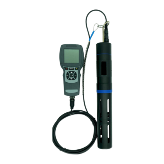
BQ401 are independently developed by BOQU Instrument. This combination can measure temperature, optical dissolved oxygen, fiber optic turbidity, four-electrode conductivity, pH, salinity, etc. The BQ401 multi-parameter handheld probe can support up to 4 types of probe measurements. When connected to instrument, these data can be automatically identified. This meter is equipped with a back light display and operation keyboard. -
Page 6: Introduction
1.1 Introduction Pic 1-1 Instrument connect sensor→ 1-2 Multi-parameter sensor 1.2 Technical Indexes Multi-parameter Sensor Indexes Range 0-20mg/L or 0-200% saturation Accuracy ±1% Optical dissolved oxygen sensor Resolution 0.01mg/L Calibration One or two point calibration Range 0.1~1000 NTU Turbidity Sensor Accuracy ±5% or ±0.3 NTU(whichever is greater)... - Page 7 Resolution 0.1 NTU Calibration Zero, one or two point calibration Range 1uS/cm~100mS/cm or 0~5mS/cm Accuracy ±1% Four-electrode conductivity Resolution 1uS/cm~100mS/cm: 0.01mS/cm sensor 0~5mS/cm: 0.01uS/cm Calibration One or two point calibration Range pH:0~14 Accuracy 0.1 Digital pH sensor Resolution 0.01 Calibration Three-point calibration Range 0~80ppt...
-
Page 8: Installation
Remark BQ600 Handheld Instrument BQ401 Handheld Connect 4pcs sensor Max multi-parameter sensor 18650 Rechargeable battery 3.7V,use for BQ600 AA battery Use for BQ401 Micro USB USB connection cable Plug Wristband Screwdriver Use to open battery cover O-ring Fluorescent cap sealed... -
Page 9: Handheld Multi-Parmeter Battery Installation
3) Close the battery cover, pay attention to the sealing ring not to fall off or be uneven, and confirm that the direction of the battery cover is correct, and tighten the screws. BQ401 Multi-parameter probe Battery Installation The handheld multi-parameter probe requires two AA batteries for normal use. Please install the batteries according to the following steps: 1) Rotate the tail cap counterclockwise to remove it, and pull out the tail plug. -
Page 10: Connection
2.3 Connection Cable connect to Instrument As shown in the figure below, align the positioning red groove of the sensor cable connector with the red groove on the meter connector, gently insert it, and then turn it clockwise until you hear a "click"... -
Page 11: Sensor Installation
Probe Installation Firstly, turn the probe removal tool counterclockwise from the top of the probe to take it out, as shown in the figure below. Insert the sensor into the port and carefully tighten the connecting nut clockwise by hand. If you feel any resistance, loosen the connection nut completely and use the probe removal tool to tighten the connection nut clockwise until it is snug. -
Page 12: Casing Installation And Connect To Sensor
Attention If a port is not installed with a probe, please install a plug. Otherwise exposure to water will cause damage or corrosion of the connector Sleeve installation and cable connection to the probe 1) Carefully push the sensor shield toward the main body until the threads of the sensor shield are aligned with the threads of the main body. -
Page 13: Operation
1. Protection cover 2. Thread 3. Main case 4.Cable probe port 3 Oper ation Short click button to turn on instrument , BQ600 instrument supports hot-swappable probe. When there is no probe, the measurement interface will display “No Signal!” after power on. If the probe is inserted again, the measurement interface will display all the probe data, as shown in the figure below Time(Minutes:second)... -
Page 14: Measurement Display
Button Instr uction Short Enter the selected menu click Confirm the setting, save the parameter value Shor t click:Button Switch unit less 2s Short Enter the calibration 长按:按键大于 2S click interface of the selected probe Long Enter the calibration click recovery interface of the selected probe Measurement Display... -
Page 15: Menu
Definition for parameters Dissolved Oxygen Salinity Turbidity Blue-green Algae Conductivity Chlorophyll Total suspended solids Oil in water CDOM Colored soluble organic matter Menu 11:25 MULT Menu Press "Menu" to enter the menu Date/Time interface. Press the "▲▼" key to System highlight the menu option you have Calibration selected, the "↙"... -
Page 16: System
3.2 System 11:25 MULTI The System menu can query and set all System parameter information, including Auto Power automatic power off, atmospheric pressure calibration, salinity value Air Pressure setting, probe information, Salinity instrument information. Use "▲▼" Probe Info keys to select up and down, press "↙" Meter Info to enter the selected submenu Auto Power... -
Page 17: Salinity
Salinity 11:25 The salinity of the sample can be set. MULTI Salinity salinity increases, dissolved oxygen value will decrease, Unit: and the meter can compensate for the Current: deviation of the dissolved oxygen Input: 000..0 value caused by the salinity value. Save Use the ▲... -
Page 18: One Point Calibration
Attention Before calibration, make sure to remove the protective cover of the DO electrode fluorescent cap with a damp sponge on the probe. 11:25 MULTI DO-Calibration Zero Point One Point Point Two Points Sensor Cap One point calibration “STD Value”:Enter the target value to be calibrated, one point calibration, it is ... -
Page 19: Sensor Cap
Two points Calibration Firstly, enter the first calibration point for calibration, the process is the same as above, after completion, press "↙" under "Click Enter" to enter the second point calibration. As shown below. Follow the prompts: "STD Value" -> "In STD Solution" -> "Confirm", and enter the second target ... -
Page 20: Turbidity Sensor Calibration
Select Read Para and press the "↙" key to enter the read fluorescent cap 11:25 MULTI Sensor Cap parameter interface. At this time, 8 sets of K0-K7 data will appear. Read Para Select Write Para and press the "↙" Write Para key to enter the write fluorescent cap parameter interface. -
Page 21: Conductivity Sensor Calibration
“In 0 NTU”:Follow the prompts to put the turbidity electrode into the 0NTU standard solution (distilled water/deionized water can be used instead), the bottom of the screen will display the real-time measurement value in NTU, and wait for the data to stabilize. “Confir m”:Press "↙"... -
Page 22: Ph Calibration
11:25 MULTI OnePoint STD Value: 001.408 mS/cm Click Enter Two points Calibration Follow the prompt "STD Value" -> "In STD Solution" -> "Confirm" to enter the first calibration point for calibration, and then press "↙" under "Click Enter" to enter the second point calibration. The process is the same 3.3.1 Two-point calibration. -
Page 23: Salinity Calibration
3.3.5 Salinity Calibration The salinity electrode supports one-point calibration and two-point calibration. One point calibration Follow the prompts: "STD Value:"->"In STD Solution"->"Confirm", enter the calibration point, put the probe into the salinity standard solution of the corresponding value, wait for the data to stabilize, and then press the "↙"... -
Page 24: Data Delete
The stored data results are named after the storage time. 21-01-13 15:32:37 means that the 54th data was stored at 15:32:37 on January 13, 2021. Use the ▲ and ▼ keys to select other data time, and press the "↙" key to enter and view the specific data results at that time point. Data Delete *Choose Yes to clear all the data currently stored, please choose carefully. -
Page 25: Maintenance
4 Maintenance 4.1 Instrument maintenance Except occasionally needing to wipe the outer surface of the meter with a damp cloth or replace the battery, the BQ600 meter does not require other maintenance. Please note that the battery compartment cannot be filled with water during normal use and replacement of the battery. 4.2 Probe Maintenance DO probe BQ600 The matched optical dissolved oxygen electrode measures the dissolved oxygen content... -
Page 26: Do Sensor
cap, the cleaning steps are as follows: i. Remove the fluorescent cap ii. Rinse the inner surface of the fluorescent cap with tap water iii. For dirt containing fat and oil, clean it with warm water with household detergent iv. Rinse the inner surface of the fluorescent cap with deionized water i. -
Page 27: Turbidity Sensor
Attention Please do not touch the fluorescent membrane on the dissolved oxygen sensor with your hands. Avoid directly applying any mechanical stress (pressure, scratches, etc.) to the fluorescent film during the use of the dissolved oxygen sensor 注意 Turbidity probe 注意... -
Page 28: Ec/Salinity Sensor
4) Check whether the housing of the sensor is damaged due to corrosion or other reasons pH Pr obe Maintenance Task Recommended maintenance frequency Calibrate the probe 3-point calibration every 30 days Replace pH probe Please replace on time according to the electrode warranty period and application environment Maintenance methods: 1) Clean the outer surface of the sensor: same as the dissolved oxygen electrode;... - Page 29 Perform a calibration operation schedule The red light on the top of Replace the battery for the probe BQ401 Probe without power the BQ401 probe is on The salinity probe appears "ovf" Put the salinity probe into the in the air solution A flashing "ovf"...
Need help?
Do you have a question about the BQ401 and is the answer not in the manual?
Questions and answers