Table of Contents
Advertisement
Quick Links
TIANJIN GREWIN TECHNOLOGY CO.,LTD.
©Tianjin Grewin Technology Co.,Ltd.We reserve all right in this document and in the information contained
within. Reproduction,use or disclosure to third partners without express authorization is strictly forbidden.
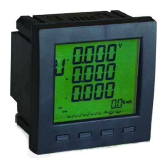
Multiple function power meter
Tianjin Grewin Technology Co.Ltd
Web:www.grewin-tech.com .
Add:DongLi Distr Tianjin City, China
Phone: +86-22-84943756
WhatsApp:+86-13072088960
Email:salesmanager@grewin-tech.com
EPM300A-1BY
User Guide
Advertisement
Table of Contents

Related Manuals for GREWIN EPM300A-1BY

Summary of Contents for GREWIN EPM300A-1BY
- Page 1 Add:DongLi Distr Tianjin City, China Phone: +86-22-84943756 WhatsApp:+86-13072088960 Email:salesmanager@grewin-tech.com EPM300A-1BY Multiple function power meter User Guide ©Tianjin Grewin Technology Co.,Ltd.We reserve all right in this document and in the information contained within. Reproduction,use or disclosure to third partners without express authorization is strictly forbidden.
- Page 2 Attention User should read this manual carefully before preparing to install, operate, serve or maintain. Below special words will across all the manual, or will stick onto the instructions to remind the potentially dangerous or to mark the important points. DANGE ‘...
- Page 3 Safety Instruction This part includes the safety instructions which should be complied before installing, serving and maintaining the equipment. WARNING! Danger Of Electric Shock,Fire And Exploding. Only profession staffs could install this equipment after complete read the manual. Don’t work alone. ...
-
Page 4: Table Of Contents
Catalogue 1. INTRODUCTION · · · · · · · · · · · · · · · · · · · · · · · · · · · · · · · · · · · · · · · · · · · · · · · · · · · · · · · · · · · · · · · · · · · · · · · · 4 1.1 Introduction ·... -
Page 5: Introduction
1.Introduction 1.1Introduction EPM300A-1BY is intelligent multi-purpose power meter which integrates the remote measuring, and remote communication functions. This meter could test, display and Remote Transfer all the common power parameters,4-ch digital inputs,2-ch relay output, multi tariff statistics, SOE record, Off-limit Alarm, over-limit alarming ,max.&... - Page 6 1.2.1.9 Demand record: record the max. Demand of total active power(+/-), demand and occurrence time of the max. Demand of total reactive power(+/-) of this month and the last month. 1.2.1.10 The mix./min. Value of the current,voltage,frequency,power factor, active/reactive/apparent power and the occurrence time of the max./min. value. 1.2.1.11 Multi-tariff: max.
-
Page 7: Specification
1.3 Specification ITEMS NOTES 3P3L,3P4L Configuration Rated value AC400V or AC100V Optional Overload Measurement:1.2 times, Instantaneous 2 times/10s Voltage Consumption <1VA per phase Impedance >400kΩ Precision RMS measurement Precision ±0.2% Rated value AC5A or AC1A Input Overload Continued 1.2 times Instantaneous 10 times/10s Current Consumption... -
Page 8: Emc Standard
1.4.EMC Standard TEST ITEMS LEVEL STANDARD high frequency anti-jamming test GB/T 15153.1/1998 Ⅲ,Ⅳ electrostatic discharge anti-jamming test GB/T 15153.1/1998 Ⅲ electrical fast transient anti-jamming test GB/T 17626.4-2008 Ⅳ surge anti-jamming test GB/T 15153.1/1998 Ⅳ power frequency magnetic fields anti-jamming test GB/T 17626.8-2006 Ⅳ,Ⅴ)... - Page 9 Fig.2 Terminal definition Terminal definition LIST VOLTAGE INPUT CURRENT INPUT POWER SUPPLY COMMUNICATION REMOTE SIGNALING SHLD 2.3 Terminal wiring 2.3.1 Voltage and current input wiring Introduction: UA :A phase voltage input UB :B phase voltage input UC :C phase voltage input ...
- Page 10 L/+ :Power supply+ N/- :Power supply - DI1 :Digital input 1 DI2 :Digital input 2 COM :Digital input common point I11 :A phase current input I12 :A phase current output I21 :B phase current input ...
- Page 11 Fig.2.3.1.2 3 phase 3 wire 2PT-3CT wiring Fig.2.3.1.3 3 phase 3 wire 2PT-2CT voltage wiring Fig.2.3.1.1 The connect method should be setted as 3 phase 4 wire Fig.2.3.1.2&2.3.1.3 should be 3 phase 3 wire Notice 1.The input voltage should not exceed the nominal input voltage.Otherwise must use PT.Short circuit is forbidden for the PT to avoid the high current.1A fuse is must in the voltage input end 2.
- Page 12 Fig.2.3.2.1 Straight-line wiring method 1:RS485/RS232 converter 2:Matched resistance 3:Computer communication port 4:Single point grounding Fig.2.3.2.2 Loop wiring method 1:RS485/RS232 converter 2:Computer communication port 3:Single point grounding 2.3.3 DI wiring Monitoring the switch value and digital value of two branch nodes.Opto-isolated input.The isolated voltage is 1500VAC.Isolated 24VDC output from the inner supply input loop power for the branch nodes.
-
Page 13: Operation Guidance
Fig.2.3.3 DI input Notice 1.The conductor cross section of the connection wire to the device should meet the following requirements: the cross section of current wires is less than 2.5mm the cross section of voltage wires is less than 1.0mm 2.In order to reduce the impact of current at startup, it is recommended for each power wire connects not more than 40 devices. -
Page 14: Buttons
7.DI condition 8.DO condition 9.Units: Current:A KA Voltage:V KV Power factor:PF Frequency:Hz Active power:KWA Fig.3.1 Screen display Apparent power:KVA Active electric energy:KWh Reactive electric energy:Kvarh Three phase unbalance degree:% 10.Current load rate 11.Communication condition 3.2 Buttons: Introduction: There are total four buttons,F1,F2,F3,F4 It's different functions under the different work mode. -
Page 15: Measure Mode
active power, total reactive power, total apparent power Active energy absolute, Reactive energy absolute, Total active energy+, Total active energy-, Phase 1 reactive, Phase 2 reactive Phase 3 reactive Phase 4 reactive Tip period energy, Peak period energy, Flat period energy, Date, Time the current month active max. - Page 16 Fig.3.3.1.2 Load rate display 3.3.2 Zone 2 display: Total phase power factor & frequency, per-phase power factor. Short press F2 to check all the pages. *Pls notice when 3 Phase 3 Wire, it can’t display per-phase power factor. Fig.3.3.1.3 Total phase power factor per-phase power factor 3.3.4 Zone 3 display Total 4 pages to display:the per-phase active power, per-phase reactive power, per-phase...
- Page 17 the current month active max. demand+/-, the current month reactive max. demand, the last month active max. demand+/- the last month reactive max. demand, max. per-phase phase voltage value, min. per-phase phase voltage value, max. per-phase wire voltage value, Fig.3.3.4 Zone 4 min.
- Page 18 Fig.3.3.5.2 Zone 5 min.&max. value display Operation: Short press F1+F2 to enter zone 5.Long press F1 or short press F1+F2 to exit. Short press F1 to modify the selected parameter. The time is the occurrence time when max./min. value occurred. Time and date cyclic display. 3.3.6 Zone 6 display This zone is for events query.Refer below pic.3.3.6 Total record...
-
Page 19: Setting Mode
Short press F3 to back to the previous page 3.3.7 Communication mark When the power meter receive the data from master computer, below mark will icon will appear. Fig.3.3.7.1 Data receiving Fig.3.3.7.2 Data transferring 3.3.8 Digital value display The digital value will displayed in the screen, refer fig.3.3.8 (DI3,DI4 is unused) Fig.3.3.8 Digital value condition 3.4 Setting mode Long press F4 to enter the setting mode. - Page 20 Fig.3.4.1 Parameter save Samples: Modify CT1,CT2,PT1,PT2 Set voltage rated primary PT1 value as 35KV, rated secondary PT2 value as 100V. PT1 rated value = set value x10 Set voltage rated primary PT1 value as 35KV, modify the rated value as 3500 as below reference fig.3.4.2 Fig.3.4.2 PT1 setting samples Set voltage rated secondary PT2 value as 100V,refer fig.3.4.3...
- Page 21 Modify communication parameter Change the communication addr. from 254 to 251.Refer fig.3.4.4 Fig.3.4.4 Communication addr. setting Modify connection mode Change the connection mode from 3 Phase 4 Wire to 3 Phase 3 Wire.Refer fig.3.4.5 Fig.3.4.5 Connection mode setting Multi-tariff setting ...
- Page 22 Power meter setting: Period Tariff Time Setting 00.00(default and can’t be changed) 00.00~08.00 Tariff 4 08.00 08.00~12.00 Tariff 2 12.00 12.00~18.00 Tariff 3 18.00 18.00~22.00 Tariff 1 22.00 22.00~22.00 Tariff 3 22.00 22.00~22.00 Tariff 3 22.00 22.00~22.00 Tariff 3 22.00 22.00~00.00 Tariff 3 Items setting: Second level menu...
- Page 23 Input :2000~2099 YEAR Year Input :1~12 DATA Month Input :1~31 Date Input :0~23 HOUR Hour TIME MINU Minute Input :0~59 Input :0~59 Second Optional :OFF/ON Energy use state The value above A IH Input :0~6000A A-VL Over current the limit alarm R-VL Return value...
-
Page 24: Communication
4. Communication 4.1 MODBUS protocol MODBUS-RTU communication protocol is common protocol which is master-slave responding connection. Master station transmit signal and address some terminal equipment.The terminal equipment transmit the responding signal to the master station. 4.2 Communication protocol address table and introduction 4.2.1 Communication protocol address table Digital quantity address table. - Page 25 40057 Display interface setting 40060 Electrical degree frozen and unfrozen state System parameter address table.Support function code 03,04 reading and function code 06,10 setting Address Type Name Value range Remark Register default:10 40065 Min.max value statistic interval 1~1440min default:1 40071 Telemetering wiring method default:...
- Page 26 Total power factor(PF) 40134 Total active power(W) 40135 Total reactive power(Q) 40136 Total apparent power(S) 40137 40138 A phase power factor(PFa) B phase power factor(PFb) 40139 C phase power factor(PFc) 40140 A phase active power(Wa) 40141 B phase active power(Wb) 40142 C phase active power(Wc)...
- Page 27 40218 Total tip tariff active power(+) absolute electrical degree cumulative value 40220 Total peak tariff active power(+) absolute electrical degree cumulative value 40222 Total flat tariff active power(+) absolute electrical degree cumulative value 40224 Total valley tariff active power(+) absolute electrical degree cumulative value 40226 Total active power(-) absolute electrical degree cumulative value...
- Page 28 40535 Low-voltage off-limit value 0~42000V 40536 Low-voltage off-limit value 0~42000V 40537 Delay time 1s~600s 40538 Enabled 0x000(disabled);0xCC33H(e 0x0000 nabled) 40540 Over-voltage off-limit value 0~42000V 40541 Over-voltage return value 0~42000V 40542 Delay time 1s~600s 40543 Enable 0x000(disabled);0xCC33H(e 0x0000 nabled) 0-99.99Hz 40550 Over-frequency off-limit value 55.0 40551...
- Page 29 Unbalanced degree:Ai/10,Ai/10, Ai = unsigned integer, unit :%. Demand statistics, support 03 and 04 function code Address Type Data definition Register 40770 Positive total active power maximum demand 40772 Negative total active power maximum demand 40774 Positive total reactive power maximum demand 40776 Negative total reactive power maximum demand 40778...
- Page 30 41013 Maximum value of B-phase power factor(PFb) 41014 Maximum value of C-phase power factor(PFc) 41015 Maximum value of A-phase active power(Wa) 41016 Maximum value of A-phase reactive power(Qa) 41017 Maximum value of A-phase apparent power(Sa) 41018 Maximum value of B-phase active power(Wb) 41019 Maximum value of B-phase reactive power(Qb) 41020...
- Page 31 41060 Occurrence time of Line-to-line voltage (Uab) maximum Value 41063 Occurrence time of Line-to-line voltage (Ubc) maximum Value 41066 Occurrence time of Line-to-line voltage (Uca) maximum Value 41069 Occurrence time of Line-to-neutral voltage (Uan ) maximum value 41072 Occurrence time of Line-to-neutral voltage (Ubn) maximum value 41075 Occurrence time of Line-to-neutral voltage (Uca) maximum value 41078...
- Page 32 41195 Occurrence time of phase A active power (Wa) minimum value 41198 Occurrence time of phase A reactive power (Qa) minimum value 41201 Occurrence time of phase A apparent power (Sa) minimum value 41204 Occurrence time of phase B active power (Wb) minimum value 41207 Occurrence time of phase B reactive power (Qb) minimum value 41210...
- Page 33 42036 42037 Temperature 42038 Voltage unbalance degree PU 42039 Current unbalance degree PI *Note: 1. In the 3-phase 3-wire system, the data in 42014~42020 are invalid and value is 0 2.The corresponding relationship of the above data(Ai) and the actual data: Voltage: U= (Ai/10), Ai denote unsigned integer, unit is V Current: I= (Ai/1000), Ai denote unsigned integer, unit is A Active power: P= Ai/10, Ai denote signed integer, unit is W...
- Page 34 Communication bit rate Introduction Reverse (setting void) Reverse (setting void) 2400 bps 4800 bps 9600 bps 19200 bps Reverse (setting void) Communication transfer format(40034):range 0~3,this mean the verify mode Verify mode code Introduction No parity verify,2 end bit Even verify,2 end bit Odd verify,1 end bit No parity verify,1 end bit Register for Slave station status (40050)
- Page 35 Bit1 Reserved Bit2 Clear all the pulse count Bit3 Reserved Bit4 Reserved Bit5 Reserved Bit6 Reserved Bit7 Reserved Bit8 Freeze all the electric energy Bit9 Unfreeze all the electric energy Bit10 Reserved Bit11 Clear demand Bit12 Reserved Bit13 Reserved Bit14 MAX/MIN value revert Bit15 Reset device...
- Page 36 Time 40057 low byte: basic display page setting Code Introduction No operation Three phase current Current unbalance degree Three phase phase- neutral voltage Three phase line-line voltage Voltage unbalance degree Frequency Power factor Three phase power factor Three phase active power Three phase reactive power Three phase apparent power Total active power, total reactive power, total apparent power...
- Page 37 *Note: 1. The high period should larger than the low period. The first period is fixed as 00:00. 2. The blank period should be set as the last period. Register 40106 the first rate setting 40092 Period 8 Period 7 Period 6 Period 5 Period 4...
- Page 38 The low order bits of register 40801 denote hour, range: 0~23 The high order bits of register 40802 denote minute, range: 0~59 The low order bits of register 40802 denote second, range: 0~59. Register of quick remote signal inquiryʊʊRegister 42000 and 42001: ...
- Page 39 Off-limit alarm caused by the device (0-->1) Undefined BIT0~BIT5 denote the number of remote signal: single 0-7 Note Note Low-power factory phase A Off-limit current phase B Reserve Over-voltage phase B,B-C Reserve Under-voltage phase B,B-C Off-limit current phase A Low-power factory phase B Over-voltage phase A,A-B Off-limit current phase C Under-voltage phase A,A-B...
- Page 40 If communication is normal, the problem is the cable or the upper computer. Tianjin Grewin Technology Co.,Ltd. FROM 2004 www.grewin-tech.com...
Need help?
Do you have a question about the EPM300A-1BY and is the answer not in the manual?
Questions and answers