
Summary of Contents for SANYU SY2000 Series
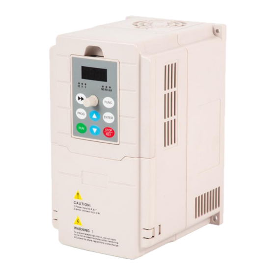
- Page 1 SY2000 Series Frequency Inverter User Manual Sanyu, control and protect your motors Shanghai Sanyu Industry Co.,Ltd.
-
Page 2: Table Of Contents
Contents Foreword ........................- 1 - Safety Precautions ..................... - 1 - 1 General technical specifications and product models ..........- 3 - Model table ......................- 5 - 2 Installation and wiring ................... - 6 - 3 Operation panel introduction ................. - 9 - 4 Peripheral equipment selection ................ -
Page 3: Foreword
Foreword Thank you for using our company's inverter. Before using it, you must read this instruction manual carefully. Please use it after you are familiar with the precautions of this product. Installation Environment: Installed indoors and in a well-ventilated place, generally should be installed vertically to ensure the best cooling effect. - Page 4 objects into the inverter. 12. .For inverters that have been stored for more than half a year, a charging experiment should be conducted before use to restore the characteristics of the filter capacitor of the inverter main circuit. When charging, the voltage regulator should be used to gradually increase the voltage to the rated value.
-
Page 5: General Technical Specifications And Product Models
1 General technical specifications and product models General technical specifications Item Description Rated voltage 380V or 220V:50HZ/60HZ frequency Input Allowable voltage Fluctuation range: ≤±20%; voltage unbalance rate: <3%; frequency: ± 5% working range Rated voltage 0~380V or 0 ~220V Output Frequency 0~999.9HZ Overload capacity... - Page 6 Automatic current Automatically limit the current during operation to prevent frequent limit overcurrent fault tripping Control the voltage during deceleration to prevent overvoltage protection Voltage stall from stopping Automatic carrier Automatically adjust carrier frequency according to load characteristics adjustment and temperature characteristics; multiple carrier modes are optional Separate VF control Easy to implement various power supply designs Textile swing...
-
Page 7: Model Table
Phase loss protection (optional), over-current protection, over-voltage Protective function protection, under-voltage protection, over-temperature protection. Overload protection, load loss protection, etc. Indoor. Free from direct sunlight, dust, corrosive gas, flammable gas, oil Location mist, water vapor, dripping or salt etc. Use derating above 1000 meters, derate 10% for every 1000 meters raised Altitude Environm Ambient temperature -10C~+40C (If ambient temperature is 40C-50C, please use derating) -
Page 8: Installation And Wiring
2 Installation and wiring 1. Basic wiring diagram - 6 -... - Page 9 2. Jumper Correspondence: VO position AO output voltage signal CO position AO output current signal Indicates that the matched resistance on 485 OFF position communication is not connected Indicates that the matched resistance on 485 ON position communication is connected 3.Control circuit terminal description: Terminal function description of control circuit Termina...
- Page 10 terminal terminals TA and TC can reach 14 TA-TC: normally open. kinds. For details, please refer to the Contact capacity: 250VAC / 2A (COSФ = 1); introduction of F2.20 output 250VAC / 1A (COSФ = 0.4), terminal function. 30VDC / 10V is the common power supply of The maximum output current is the analog input terminal circuit...
-
Page 11: Operation Panel Introduction
3 Operation panel introduction Panel indicator description Symbol Name Function Forward indicator The inverter is running forward, Reverse indicator The inverter is running reverse。 Warning indicator Lights up when the inverter failure When the light is on, it means that the LED display Voltage indicator content is voltage data When the light is on, it means that the LED display... -
Page 12: Peripheral Equipment Selection
4 Peripheral equipment selection For inverters of different power levels, the recommended values of air switch MCCB, contactor capacity and copper core insulated conductor cross-sectional area are shown in the table below Recommended table of inverter input and output wiring specifications Incoming protection Power cable Signal line... -
Page 13: Parameter Monitor And Fault Record
5 Parameter monitor and fault record Group d-Monitoring parameter group Amend Code Setting Range Default Value Item Description ment Output frequency ◆ d-00 0.00~999.9Hz 0.1HZ 0.0Hz (Hz) Setting frequency ◆ d-01 0.00~999.9Hz 0.1HZ 0.0Hz (Hz) ◆ d-02 Output voltage (V) 0~999V ◆... - Page 14 0 ~ FFFFH 0: Run / Stop 1: Reverse / Forward 2: Jog 3: DC braking 4: Reserved 5: Overvoltage limit 6: Constant speed frequency down 7: Over-current limit 8 ~ 9: 00-zero speed / 01-acceleration / 10-deceleration ◆ d-26 Inverter status / 11-constant speed 10: Overload pre-alarm 11: Reserved...
- Page 15 Inverter output short circuit or Check motor wiring grounded Iverter instantaneous overcurrent Refer to overcurrent solution Power module ESC1 Control board abnormal or failure Ask service from the manufacturer serious interference Power device damage Ask service from the manufacturer The ambient temperature is too Decrease ambient temperature high Radiator...
-
Page 16: Parameter Summary And Instructions
6 Parameter summary and instructions Parameter Description ○ —Parameters that can be modified in any state × —Parameters that cannot be modified in running state ◆—Actual detection parameters, which cannot be modified ◇ —Manufacturer parameters, which are limited to manufacturer modification, and users are prohibited Group F0-basic operating parameters Default Amend... - Page 17 frequency Processing 0:Zero speed operation when Lower F0.07 1:Run at the lower limit frequency 0~2 × limit frequency 2:Stop reaching Digital setting 0.0~Upper The value is the initial value of 10.0H ○ F0.08 of operating limit frequency digital setting frequency frequency LED ones: power-off storage 0:save...
- Page 18 This setting is the lifting cut-off frequency point during manual torque boost Torque boost 15.0H F0.15 cutoff 0.0~50.0Hz × frequency For occasions requiring silent operation, the carrier frequency can be appropriately increased to meet the 2.0~16.0KH requirements, but it will increase the Carrier heat generation of the inverter.
- Page 19 Group F1-auxiliary operating parameters Default Amend Code Item Description Setting range Value ment LED ones: starting mode 0:starting from the starting frequency 1:DC braking first and then starting from the starting frequency LED tens: Power failure or abnormal F1.00 Starting method 0000~0011 ×...
- Page 20 Starting 0.0~Upper frequency of ○ F1.05 limit 0.0Hz DC braking at frequency stop 0.0~50.0%× Voltage of DC ○ F1.06 Motor rated 0.0% braking at stop voltage DC braking F1.07 0.0~30.0s 0.0s × time at stop DC braking F1.08 waiting time at 0.00~99.99s 0.00s ×...
- Page 21 LED thousands: Power-down storage options 0:storage 1:do not storage ○ -Upper 5.0Hz Multi-speed frequency to F1.17-P1.35 to determine the operating F1.17 frequency 1 upper frequency, time and direction of each frequency section. ○ -Upper 10.0H The multi-step speed frequency can be Multi-speed frequency to set continuously from -upper limit...
- Page 22 time selection 1 LED tens: Speed segment 2 acceleration and deceleration time 0 ~ 1 LED Hundreds : Speed segment 3 acceleration and deceleration time 0 ~ 1 LED Thousands: Speed segment 4 acceleration and deceleration time 0 ~ 1 LED ones: Speed segment 5 acceleration and deceleration time 0 ~...
- Page 23 ACI upper limit limit frequency [F0.05]. 100.0 ○ F2.07 corresponding setting This parameter is used to filter the input Analog input signal of AVI, ACI and panel ○ F2.08 signal filtering 0.1~5.0s 0.1s potentiometer to eliminate the influence time constant of interference。...
- Page 24 terminal control 1: Two-wire control mode 2 mode 2: Three-wire control mode 1 3: Three-wire control mode 2 Terminal 0: terminal running command is invalid function when power on F2.19 detection 1: terminal running command is valid 0~1 × selection at when power on power-on Relay...
- Page 25 The function code is the frequency modification rate when setting the UP / DOWN frequency by the UP / DOWN terminal, terminal 0.1Hz~99.9 1.0Hz/ ○ F2.27 that is, the UP / DOWN terminal and modification Hz/s the COM terminal are shorted for one rate second, and the amount of frequency change...
- Page 26 than the given amount of PID, the output frequency of the inverter is required to decrease (that is, to reduce the feedback signal). 2: Negative effect When the feedback signal is greater than the given amount of PID, the output frequency of the inverter is required to increase (ie, reduce the feedback signal).
- Page 27 2). If the tens place of F3.00 is 2, it is given by pressure. This parameter is consistent with the unit of F3.18. When the level of the feedback channel Feedback and the set channel are inconsistent, this ○ F3.02 0.01~10.00 1.00 channel gain...
- Page 28 threshold the given value, the inverter will leave coefficient the sleep state and start working after the delay waiting time defined by F3.13; this value is the percentage of the PID set value. Sleep delay Set sleep delay time ○ F3.12 0.0~999.9s 100.0s...
- Page 29 0.00~99.99 10.00 ○ F3.18 Sensor range Set the maximum range of the sensor (MPa, Kg) Group F4-Advanced function parameters Default Amend Code Item Description Setting range Value ment 0~500V:3 Motor rated Model F4.00 × voltage 0~250V:2 setting Motor rated Model Motor parameter setting F4.01 0.1~999.9A...
- Page 30 1: Alarm but maintain the status quo operation 2: Alarm and stop according to the set method LED Thousands : Shock suppression selection 0: invalid 1: valid The motor overload protection factor is Motor overload the percentage of the motor rated F5.01 protection 30%~110%...
- Page 31 pre-alarm signal. 0: Invalid Jog priority F5.12 1: When the inverter is running, the 0~1 × enable jogging priority is the highest Oscillation ○ F5.13 suppression 0~200 When motor vibration occurs, it is factor necessary to set F5.00 thousands to be Amplitude effective, turn on the vibration ○...
- Page 32 inverter will decide whether to protect or maintain the current operation according to the setting of the communication failure action mode. When the value is set to 0.0, RS485 communication timeout detection is not performed. This function code defines the end of the inverter data frame reception and sends the intermediate time interval of Local response...
- Page 33 corresponding setting is a percentage relative to the setting maximum output frequency External pulse X5 upper limit -100.0%~10 100.0 ○ F7.07 corresponding 0.0% setting Group F8-Management and display parameters Default Amend Code Item Description Setting range Value ment For example: F8.00 = 2, that is, select Operation the output voltage (d-02), and then the monitoring...
-
Page 34: Communication Protocol
7 Communication Protocol (The following data are all hexadecimal) 1、RTU mode and format When the controller communicates on the Modbus bus in RTU mode, each 8-bit byte in the information is divided into two 4-bit hexadecimal characters. The main advantage of this mode is that the density of characters transmitted is higher than that of ASCII mode at the same baud rate, each message must be transmitted continuously. - Page 35 2102H Set frequency (two decimal places) Output frequency ( two decimal 2103H places) 2104H Output current (one decimal places) 2105H Bus voltage (one decimal places) output voltage(one decimal 2106H places) Inverter temperature (one decimal 210DH places) PID Feedback value (two decimal 210EH places)...
- Page 36 Address Function Starting data address Data(2Byte) CRC CHK Low CRC CHK High Data analysis: 01H Inverter address 03H Function code 2102H Starting address 0002H To read the number of addresses, I.e. 2102H and 2103H F76FH 16-bit CRC check code Response information frame format(Return frame): Address Function DataNum*2...
-
Page 37: Regular Inspection And Maintenance
Address Function Starting data address Data(2Byte) CRC CHK Low CRC CHK High Data analysis: 01H Inverter address 06H Writing function code 2000H Control command address 0001H Stop command 43CAH 16-bit CRC check code Response information frame format(Return frame): Address Function Starting data address Number of Data(Byte) CRC CHK Low... - Page 38 (5) Is the cooling fan of the inverter running normally?。 2: Regular maintenance Regular maintenance The user can conduct regular inspections of the inverter in the short-term or 3-6 months according to the usage, to eliminate hidden troubles and ensure long-term stable operation. When the inverter checked, the power must be cut off.
- Page 39 China Technical Service Headquarter Manufacturer: Shanghai Sanyu Industry Co.,Ltd. Address: Room 723,No.800 Shangcheng Road, Shanghai,China Tel:+86-21-65046976 Fax:+86-21-516865815 Postal code:200120 Website: www.sanyuacdrive.com E-mail:infor@sanyuinverter.com - 1 -...