Advertisement
Technical Instructions
WARNING
!
Read this Manual BEFORE using this equipment.
Failure to read and follow all safety and use infor-
mation can result in death, serious personal injury,
property damage, or damage to the equipment.
Keep this Manual for future reference.
WARNING
!
FAiLURE tO COMpLY WitH pROpER iNStALLAtiON ANd
MAiNtENANCE iNStRUCtiONS COULd CONtRiBUtE tO tHE
VALVE FAiLURE.
this Hot Water Master tempering Valves cannot be used for
tempering water temperature at fixtures. Severe bodily injury
(i.e., scalding or chilling) and/or death may result depending
upon system water pressure changes and/or supply water
temperature changes. ASSE standard 1016, 1069 or 1070 listed
devices should be used at fixtures to prevent possible injury.
These Hot Water Tempering Valves are designed to be
installed at or near the boiler or water heater. They are not
designed to compensate for system pressure fluctuations and
should not be used where ASSE standard 1016, 1069 or 1070
devices are required. These valves should never be used to
provide "anti-scald" or "anti-chill" service.
The components of the system must be of materials with a
construction capable of withstanding the high limit output tem-
peratures of the water heating source.
WARNING
!
Need for periodic inspection and Yearly Maintenance:
Periodic inspection and yearly maintenance by a licensed con-
tractor is required. Corrosive water conditions and/or unauthor-
ized adjustments or repair could render the valve ineffective for
service intended. Regular checking and cleaning of the valve's
internal components and check stops helps assure maximum
life and proper product function. Frequency of cleaning and
inspection depends upon local water conditions.
WARNING
!
You are required to consult the local building and plumbing
codes prior to installation. If the information in this manual is
not consistent with local building or plumbing codes, the local
codes should be followed. Inquire with governing authorities for
additional local requirements.
WARNING
!
Flush all pipes thoroughly before installation. Installation and
field adjustment are the responsibility of the installer.
AiR OpERAtEd:
Rigid Stainless Bulb
Direct Action
744-1270
Reverse Action
744-1271
Rigid Copper Bulb
Direct Action
744-1213
Reverse Action
744-1214
Specifications
n
Operation
. . . . . . . . . . . . . . . . . . . . . . . . . . . . . . . . . . . .
Adjustment Dial Range—Standard 50 to 350°F (10 to 177°C)
Maximum Supply Pressure (air or water)
at Room Temperature
. . . . . . . . . . . . . . . . . . . . . . . . . .
Air Consumption (max.)
. . . . . . . . . . . . . . . . . . . . . . . . .
Maximum Operating Pressure
Maximum Operating Temperature
Temperature Response
. . . . . . . . . . . . . . . . . . . . . . . . . . . . . . . . . . .
Mounting
. . . . . . . . . . . . . . . . . . . . . . . . . . . . . . . . . . . . . . . . . . . . . . . . . . . . . . .
Air or Water Connections
. . . . . . . . . . . . . . . . . . . . . . . . . . . . . . . . . . . . .
Drain Connection (water only)
Shipping Weight
. . . . . . . . . . . . . . . . . . . . . . . . . . . . . . . . . . . . . . . . . .
Sensitivity (adjustable)
. . . . . . . . . . . . . . . . . . . . . . . . . . . . . . . .
Maximum Pressure on Wells
Stainless Steel no. 744-082
Copper no. 744-111
. . . . . . . . . . . . . . . . . . . . . . . . . . . .
Well Dimensions
. . . . . . . . . . . . . . . . . . . . . . . . . . . . . . . . . . . . . . . . . . . .
IS-P-TC744-1
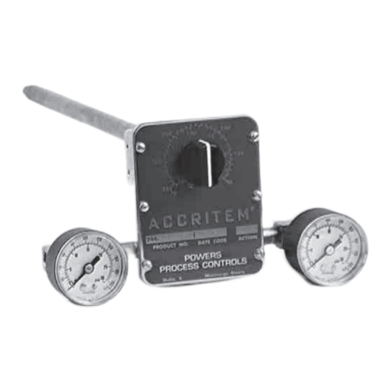
Accritem Controller
Model 3
WAtER OpERAtEd:
Rigid Stainless Bulb
Direct Action
744-1217
Reverse Action
744-1218
Direct or Reverse Acting
35 psi (241.3 kPa)
218 cm 3/s (800 SCIM)
1724 kPa (250 psi)
. . . . . . . . . . . . . . . . . . . . . .
400°F(204°C)
. . . . . . . . . . . . . . . . . . . . . . . .
0.5°F(0.3°C )
1/2" NPT
1/8" NPT
1/4" NPT
. . . . . . . . . . . . . . . . . . . . . . . . . . . . . . . .
4 lbs. (1.8 kg)
3.1 to 27.9 kPa/C
(1/4 to 2-1/4 psi/F)
1125 psi (7756 kPa)
. . . . . . . . . . . . . . . . . .
525 psi (3619 kPa)
See page 6
Advertisement
Table of Contents

Subscribe to Our Youtube Channel
Related Manuals for Watts Industries POWERS Accritem Controller 3


Summary of Contents for Watts Industries POWERS Accritem Controller 3
- Page 1 IS-P-TC744-1 Accritem Controller Model 3 Technical Instructions WARNING Read this Manual BEFORE using this equipment. Failure to read and follow all safety and use infor- mation can result in death, serious personal injury, property damage, or damage to the equipment. Keep this Manual for future reference.
- Page 2 Operation Instructions Direct Action Controller Figure 1 A temperature change in the medium being controlled creates a Positions “B” and “D” (dotted) show change in length of the sensitive tube . An increase in tempera- pivot point (“B”) and spring when controller is REVERSE acting.
- Page 3 Select sensitive element location with care to insure satisfac- Installation Instructions tory results. Bulb must project entirely into the liquid or air being General Instructions controlled. Flush or blow out all lines before making final connections. Put supply pressure through all control lines and check for leaks. Figure 5.
- Page 4 Figure 7 6. Install cover plate (6 screws) 7. Install adjustment knob with set screw . The knob indicator (white line on side of knob) should be opposite the dial marking corresponding to the room temperature. Tighten the knob set screw very firmly. 8.
- Page 5 DATE CODE ACTION PRODUCT NO. 1/8" NPT 1/8" NPT Return Air Supply POWERS PROCESS CONTROLS Parts Skokie, Il. Mississauga, Ontario Water Operated Section “A–A” Front View of Cover 1/4" NPT to Drain (Water Operated Only) 57 (2-1/4") 40 (1-19/32") 292 (11-1/2") 13 (1/2") Reverse Acting Spring Location Water Operated...
- Page 6 Accessories Dimensions: Millimeters (Inches) Accessory Kit No. 744-107 (Dotted line item not included) Provides materials necessary to reduce the incoming air supply pressure to within the supply pressure range of the Accritem Pressure-Reducing Valve Accritem Controller 1/8" Nipple 1/4 x 1/8 Reducing Bushing Place 1/4"...
- Page 7 Operation Continued Additional information on controller action and applications. Figure 8. APPLICATION HEATING COOLING MIXING ACTION: DIRECT Acting Normally OPEN valve Normally CLOSED valve Hot piped to Normally OPEN port of valve Valve OPENS on air failure Valve CLOSES on air failure Valve opens to HOT flow on air failure REVERSE Acting...
- Page 8 WARNING: This product contains chemicals known to the State of California to cause cancer and birth defects or other reproductive harm. For more information: www.watts.com/prop65 Warranty The Seller warrants that the equipment manufactured by it and covered by this order or contract is free from defects in material and workmanship and, without charge, equipment found to be defective in material or workmanship will be repaired, or at Seller’s option replaced F .O.B.
Need help?
Do you have a question about the POWERS Accritem Controller 3 and is the answer not in the manual?
Questions and answers