Table of Contents
Advertisement
Quick Links
Advertisement
Table of Contents

Summary of Contents for Aperia Technologies Halo Connect GW-10
- Page 1 Halo connect INSTALLATION GUIDE for SLEEPER cab vehicles Document Number: 91-00008374 Rev. R01 June 2022 Aperia Technologies, Inc. 1616 Rollins Rd. Burlingame, CA 91040 Phone: (650) 741-3231 Fax: (415) 524-2449 www.aperiatech.com © 2022 Aperia Technologies, Inc.
-
Page 2: Table Of Contents
Contents Important Safety Information Section 1: Components & Tools Section 2: Block Diagram & Install Layout Section 3: Plan component installation Section 4: Where to Find Power Sources Section 5: Mount GPS antenna mounting and route cable Section 6: Mount TPMS antenna Section 7: Route GPS and TPMS antenna cables into the cab Section 8: Apply gateway ID label to door Section 9: Mount the gateway... -
Page 3: Section 1: Components & Tools
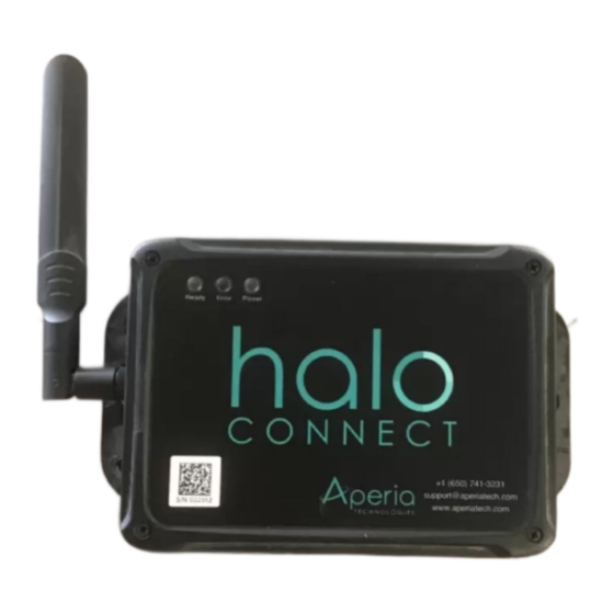
SECTION 1. Components & Tools Halo Connect system components *Power harness connector will vary based on vehicle type (RP1226 connector shown) Gateway Information Model: GW-20 S/N: 031776 MAC: 11-22-33-44-EE-FF www.aperiatech.com +1 (650) 741-3231 support@aperiatech.com Required tools and other consumables TOOL/CONSUMABLE DESCRIPTION PURPOSE Small Impact Driver Self-tapping screws, cabin panels... -
Page 4: Section 2: Block Diagram & Install Layout
SECTION 2. BLOCK DIAGRAM & INSTALL LAYOUT GATEWAY Install Layout Option 1 Gateway: Under sleeper bunk GPS Antenna: Top fairing bracket Power Source: Under sleeper bunk POWER TPMS Antenna: Low on rear of truck OPTION 2 POWER OPTION 1 TPMS GATEWAY POWER OPTION 2... -
Page 5: Section 3: Plan Component Installation
SECTION 3. PLAN COMPONENT InstallATION Power Source GPS Antenna Preferred Source: Inverter power & ground studs Preferred Location: Top faring bracket or roof Alt. Source 1: Direct to battery Alternative Location: Top of dashboard Alt. Source 2: Fuse panel Transmissions are blocked by Gateway power source should be: metal, but will pass through •... -
Page 6: Section 4: Where To Find Power Sources
SECTION 4. WHERE TO FIND POWER SOURCES Preferred Power Source: Power & ground studs on power inverter under bunk Power Harness PN: CB-DC10A Vehicle Side Of Power Harness Common location 3/8" ID ring terminals w/ 5/16" ID conversion washers Alternative Power Source 1: RP1226 Telematics Connector Power Harness PN: CB-RPS16A and CB-RPS16A-P1 Common locations in dash* Vehicle Side Of Power Harness... -
Page 7: Section 5: Mount Gps Antenna Mounting And Route Cable
SECTION 5. MOUNT GPS ANTENNA AND ROUTE CABLE Step 5.1: Clean and prepare the GPS antenna mounting surface and cable routing area A. Clean the surfaces where the GPS adhesive and adhesive cable tie mounts attach. Step 5.2: Attach the GPS antenna A. - Page 8 SECTION 5. MOUNT GPS ANTENNA AND ROUTE CABLE (CONT'D) Step 5.3: Route GPS antenna to bottom of cab A. Route the loomed antenna cable to the bottom of the cab, towards the cabin access hole, securing the cable at least every 12 inches. GPS CABLE ROUTING GUIDELINES •...
-
Page 9: Section 6: Mount Tpms Antenna
SECTION 6. MOUNT TPMS Antenna Step 6.1: Install TPMS bracket A. Attach the provided TPMS bracket to the rear of the cab in your previously selected location. Be sure the TPMS antenna will protrude below the bottom of the cab TPMS Test fit the TPMS antenna prior to attaching bracket to make sure it will protrude past the bottom of the cab and will... -
Page 10: Section 7: Route Gps And Tpms Antenna Cables Into The Cab
SECTION 7. ROUTE GPS & TPMS ANTENNA CABLES INTO THE CAB Step 7.1: Find or make the cab access hole A. Use the existing access hole located during the planning step, or make a 1/2 inch access hole, in the bottom of the cab to route cables for externally mounted antennas into the cab. -
Page 11: Section 8: Apply Gateway Id Label To Door
SECTION 7. ROUTE GPS & TPMS ANTENNA CABLES INTO THE CAB Step 7.2: Route cables to cabin access hole A. Place a cable tie mount 1-4 inches from TPMS antenna. B. Route the GPS and TPMS to the access hole, securing cabling with zip ties and cable tie mounts under cab at least every 12 inches. -
Page 12: Section 9: Mount The Gateway
SECTION 9. MOUNT THE GATEWAY Step 9.1: Mount the gateway inside cab A. Mount the gateway in the previously selected location. B. Use incuded self drilling screws when mounting direct to sheet metal or a sheet metal support behind a trim panel. GATEWAY C. -
Page 13: Section 10: Connect Power Harness To Vehicle
SECTION 10. CONNECT POWER HARNESS TO VEHICLE Step 10.1: Connect power harness to vehicle The positive wire of the power ca- ble must be fused. An un-fused power cable may over-heat and lead to a vehicle fire. POWER OPTION 2 POWER Fuse Rating: 2 Amp OPTION 1... - Page 14 SECTION 10. CONNECT POWER HARNESS TO VEHICLE (CONT'D) ALTERNATIVE POWER SOURCE 2: RP1226 Connector RP1226 power harness part #s CB-RPS16A and CB-RPS16A-P1 A. Connect the RP1226 harness directly to the OE connector in the vehicle. If RP1226 connector is already populated with other devices, disconnect them. B.
- Page 15 SECTION 10. CONNECT POWER HARNESS TO VEHICLE (CONT'D) ALTERNATIVE POWER SOURCE 2: Fuse panel Fuse tap power harness - Part #s CB-FT10A A. Locate fuse panel. B. Select a fuse on a battery circuit. C. Remove selected fuse from panel. Existing D.
-
Page 16: Section 11: Route Cables And Connect To Gateway
SECTION 11. Route Cables & Connect to gateway POWER OPTION 2 POWER TPMS OPTION 1 TPMS GATEWAY Step 11.1: Route antenna cables and power harness to gateway and bundle A. Uncoil and detangle antenna cables and power harness for easier bundling. B. - Page 17 SECTION 11. Route Cables & Connect to gateway (CONT'D) Step 11.3: Store bundle and secure exposed cables A. Store excess cabling in an open space behind a trim panel. B. Secure cable near gateway using a cable tie mount to prevent snagging. Do not put tight bends in cables near connectors.
-
Page 18: Section 12: Prepare For Activation
SECTION 12. PREPARE FOR ACTIVATION Step 12.1: Download Halo Connect mobile app A. Using a mobile or tablet device with iOS or Android 6.0 or later, search for "Halo Connect" in the app store & download the Halo Connect app. App Link: http://aperiatech.com/HC-app Step 12.2: Connect antennas and power cable to gateway A. -
Page 19: Section 13: Begin Activation & Install Sensors
SECTION 13. BEGIN ACTIVATION & INSTALL SENSORS Step 13.1: Download Halo Connect mobile app A. Open mobile app and follow workflow in section 14 until step 11, then proceed below. B. The sensors are marked with the specific positions they must be installed on. C. -
Page 20: Section 14: Gateway Activation Workflow
SECTION 14. GATEWAY ACTIVATION WORKFLOW Open the Halo Connect app and Scan the QR code on the door When prompted enter the choose: "Set Up a New Vehicle" label. gateway serial number found on the door label. Delivery Fleet ZZZFD31 Choose "reconfigure"... - Page 21 SECTION 14. GATEWAY ACTIVATION WORKFLOW (Cont'D) Select "Pair All Sensors at Once" Scan the QR code on the sen- The sensors will begin pairing and confirm once complete. sor pack label. Choose "Submit and Run Diagnostics." Enter the vehicle odometer reading. Tap each tire to enter tire details and, if Enter required tire detail, then tap "Submit &...
-
Page 22: Section 15: Regulatory Information
SECTION 15: Regulatory INFORMATION RF Exposure This equipment complies with FCC and IC radiation exposure limits set forth for an uncontrolled environment. This equipment should be installed and operated with minimum distance of 20 cm between the radiator and your body. This transmitter must not be co-located or operating in conjunction with any other antenna or transmitter. Cet équipement est conforme aux limites d'exposition aux radiations de la FCC et de l'IC définies pour un environnement non contrôlé. - Page 23 SECTION 15: Regulatory INFORMATION (CONT'D) Changing the world one revolution at a time Supplier's Declaration of Conformity Responsible party details Aperia Technologies Company name: Address: 1616 Rollins Road, Burlingame, CA 94010 Contact Person: Brandon Haws Email: bhaws@aperiatech.com Phone No.: +1-844-RUN-HALO Fax No.:...
Need help?
Do you have a question about the Halo Connect GW-10 and is the answer not in the manual?
Questions and answers