
Related Manuals for Zone Ozonetech Journey

Summary of Contents for Zone Ozonetech Journey
- Page 1 VERSION 1.4.00 May 2022 INSTALLATION GUIDE Ozonetech Journey IMPORTANT Before proceeding with the system installation, Be sure to have carefully read and understood all instructions provided in this guide.
- Page 3 This document includes important indications to prevent serious injuries both to the technician installer and to the users. system made by Zone Technologie Électronique Inc. is fully Ozonetech Quick Connect programmable (all settings are flexible).
-
Page 5: Table Of Contents
TABLE OF CONTENTS 1. General description ......................1 1.1 Essential connection ....................1 1.2 Technical specifications ....................1 2. Installation ..........................2 Warning ..........................2 2.1 Mechanical Installation Notes ..................2 2.2 Electrical Installation Notes..................2 2.3 Module Installation ...................... 3 2.4 Outside Temperature Sensor Installation.............. -
Page 7: General Description
1. GENERAL DESCRIPTION The Ozonetech idle reduction module is an eco-friendly automotive fuel saving and CO2 reduction system. This system will reducing unnecessary idling and will monitor the battery voltage. Whenever battery voltage drops below preset value it will start the vehicle. If during the start engine doesn’t start within 10 seconds, the module will wait 10 seconds before repeating startup for the second time. -
Page 8: Installation
2. INSTALLATION ZONETECH ODULE WARNING Pay particular attention to the safety and installation instructions in this guide to prevent damage to the unit or vehicle as well as serious injuries to anyone working on the vehicle, occupants or you. The installation technician should have a good understanding of vehicular electrical and electronic systems to perform a compliant and safe installation. -
Page 9: Module Installation
INSTALLATION (cont.) 2.3 MODULE INSTALLATION: A. Remove interior trunk carpeting. Disconnect the vehicle battery, only negative post (use 10mm socket). B. Remove the trunk cover panel (4 push pins) and slide out the panel holders. C. Open de screw covers and remove the two T-30 screws to remove the left side panel. - Page 10 INSTALLATION (cont.) D. Remove the rear panel (4 push pins). Remove 4 screws to remove the bottom cover F. Open the cover and remove T-20 screw to remove the seat belt cover panel. G. Remove three screws on the trunk left side panel.
- Page 11 INSTALLATION (cont.) H. Remove the panel. NOTE: Disconnect the wires inside before remove the panel. Remove the push pins in the rear end of the roof cover. J. Disconnect the left connector of the RF module that is inside the roof. K.
- Page 12 INSTALLATION (cont.) L. Attach the C2 T- Harness and the USB cable the vehicle Harness. M. Fix the module to the left column, connect the C2 T-Harness and attach the harness like the image. Remove the left rear light (Pull the center of the 2 push pins).
-
Page 13: Outside Temperature Sensor Installation
INSTALLATION (cont.) Connect the brown wire from the C2 Harness to the White/Blue wire in the vehicle harness and isolate it. NOTE: The basic installation is complete. If there are no temperature control, Keyless Mode or Anti-theft Mode panels can be reinstalled. 2.4 OUTSIDE TEMPERATURE SENSOR INSTALLATION A. - Page 14 INSTALLATION (cont.) C. Push cable terminals, provided in the kit, into the connector housing. Terminal Positions: A = red B = black Connect the external temperature sensor provided in the kit to the cable harness. D. Attach the probe to the harness of the vehicle. NOTE: Leave some extra harness in case of future service.
-
Page 15: Hood Switch Installation
INSTALLATION (cont.) 2.5 HOOD SWITCH INSTALLATION A. Remove the skid plates in the left side: one in the back door and two in the front door. B. Route the C1 harness towards the front of the vehicle on the driver side. C. - Page 16 INSTALLATION (cont.) D. Remove the panel beside the dashboard. E. Remove 2 screws under the panel below the steering wheel and remove the panel.
- Page 17 INSTALLATION (cont.) F. Remove the grommet for the clutch and drill a 3/8” hole on it. G. Reinstall the grommet and pass the hood switch wires through it. H. Remove the screw in the front-left fender to, insert the bracket and reinstall the screw.
- Page 18 INSTALLATION (cont.) Attach the hood switch to the bracket. Hood Switch Magnet J. Insert the terminals in the housing. A = Yellow/black B = Blue Connect hood sensor harness to the module harness and fix the excess of cable. K. Apply a small amount of grease to the top of the hood sensor.
-
Page 19: Inside Temperature Sensor Installation
INSTALLATION (cont.) 2.6 INSIDE TEMPERATURE SENSOR INSTALLATION A. Attach the cable to the vehicle harness as shown in the picture. Push cable terminals into the connector housing and connect the sensor. Same procedure of the external sensor. 2.7 KEYLESS SWITCH INSTALLATION A. - Page 20 INSTALLATION (cont.)
-
Page 21: Programming
3. PROGRAMMING The Ozonetech module is an eco-friendly automotive fuel saving system. It functions primarily on a timer that counts down idling time. During an idling period, after countdown is finished, the systems will shut down the engine on the assumption that fuel is being wasted. The system may void the countdown of the timer if certain conditions aren’t meat. -
Page 22: Initiating Usb Communication
PROGRAMMING …(cont.) • The vehicle is able to restart by manually turning the key. • The key is set to the run position, without the engine running. • The green LED on the module is blinking quickly (It should blink every half second). •... -
Page 23: Software Description
Ozonetech QuickConnect SOFTWARE MAIN PROGRAMMING WINDOW – Compact view Ozonetech QuickConnect SOFTWARE MAIN PROGRAMMING WINDOW – Full view NOTE: This manual will present the Compact view. If you need access to more Zone Technologies and ask for the Advanced functions please contact Progammer’s Guide. -
Page 24: Menu Description
PROGRAMMING …(cont.) 3.5.1 Menu description: This tab allows you to manage your setup files (*.ozt) within your computer. You can save, load and create new setup files. The « Configuration » tab is used to select which USB port you want to use for communication. NOTE: The menu configuration is only active if you are disconnected. - Page 25 État module: (Module State) Mudule information window used to regroup module information found in the lower status field of the O-Zone- Tech II software and voltage input from battery 1 and 2. This window was required for laptop users before software scrollbar implementation.
-
Page 26: Box Version
(When programmed engine start retry as been reached) 3.5.4 Box Version Version: Used to identify hardware (module Firmware) and software revision. Hardware : Indicates the firmware version programmed in the module. Software : Indicates O-Zone-Tech II computer software version. -
Page 27: Box Reading All
PROGRAMMING …(cont.) 3.5.5 Box Reading All: Reading All: - Idle times : ......Real time display in days, hours, minutes and seconds of the five idling timers and the input timer. A click on « E » button will reset all timers and a click on « R » button will reset the associated timer (positioned to the left of it). -
Page 28: General Tab
PROGRAMMING …(cont.) 3.5.7 GENERAL TAB: The program first opens up on the ‘‘General’’ thumbnail. You will need to set the Vehicle Number (ID), program the Keyless Mode Duration, Anti-theft input and select individual inputs that may have a negative polarity. •... -
Page 29: Idle Tab
PROGRAMMING …(cont.) 3.5.8 IDLE TAB: This menu gives access to all idle controlling parameters. The proper setup of the inputs is an important functionality factor. When any of these inputs are triggered, the virtual LEDs beside them will light up green. These Inputs will act as conditions to allow or deny the system’s control of the engine. -
Page 30: Start Tab
PROGRAMMING …(cont.) • Digital Inputs: Setup options for digital inputs. This setup section works in conjuncture with the ‘‘Input polarity’’ section on the ‘‘General’’ thumbnail. Selection: Activates the inputs. Inversion: Inverts the system’s logic reading of the input. For example, when a positive input is inverted, it will be triggered when it is not at 12Volts. - Page 31 PROGRAMMING …(cont.) • Conditions: Battery voltage (V): Primary battery’s lower level trigger. The vehicle is automatically restarted when this minimum voltage is reached. Valid.(s): Validation time before the engine restart for low voltage. Temperature in (°C/°F) Heating Min: Minimum allowed temperature inside the vehicle at which the system will restart the vehicle.
-
Page 32: Auxiliary Tab
PROGRAMMING …(cont.) 3.5.10 AUXILIARY TAB: • Auxiliary outputs: Output 1, 2, 5 & 6 are positive outputs. These outputs are protected by internal auto-resettable breaker. Do not use them for more than 500mA each and 1A total if more than one is in use. More than 15 parameters can be program: Relay1: Follow Relay1 in the general tab. -
Page 33: Download And Upload Of Configurations
PROGRAMMING …(cont.) 3.6 DOWNLOAD and UPLOAD of configurations: Although the status of inputs and outputs are presented in real time the changes in parameters require an UPLOAD command. The buttons MODULE PC can be found in all tabs. DOWNLOAD: At the beginning of any configuration a download from the module to PC is recommended. After a download the software will present the configuration that is already been used by the module. -
Page 34: Analyze Idle
The “Quit” menu is used to close the acquire windows and go back in the main menu. B. The “Acquire” button is used to read all counter information in the O-Zone-Tech CHR module. NOTE: Click on “Acquire” create an “idl” file in the folder showed on “E”. The file name follows the vehicle serial number if not previously created. -
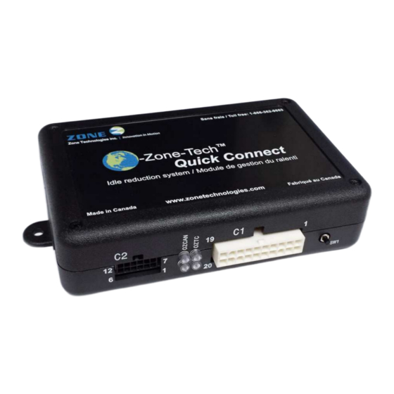
Page 35: Pinout
O-Zone-Tech module power inputs. Power source C2.6, C2.12 inputs (C2.6 = Negative (GND) signal, C2.12 = 12Vdc) Module USB 2.0 connector O-Zone-Tech to PC communication port communication Temperature sensor input signals. C1.15 & Temperature sensor Internal temperature sensor = Optional C1.17 External temperature sensor = Standard C1.13... - Page 36 CONNECTION …(Suite) Connector Wire Color Description USB connection, link between O-Zone-Tech RAM module and computer. White 12V Ignition sense input N/A (No wire) Not used N/A (No wire) Not used N/A (No wire) Not used N/A (No wire) Not used...
-
Page 37: Troubleshooting
6. TROUBLESHOOTING Most common problems and fixes Engine does not start when the key is in START position: • Check cable connections and fuses. Engine does not restart when in IDLE or KEYLESS modes: • Check the cable connections and fuses. •... - Page 38 Notes...
- Page 39 Notes...
- Page 40 Zone Technologie Électronique Inc. guarantees every component that it produces for a period of 24 months starting on the date of the purchase or of the delivery. The products of Zone Technologie Électronique Inc are verified, inspected and recognize as exempt of any fabrication default.
- Page 41 Toll free : 1 866 362-9663 Phone : 450 572-1476 Technical support Extension #205 Administration Extension #221 450 572-0898 Fax : 9000, boul. Industriel, Chambly (Québec) J3L 4X3...
Need help?
Do you have a question about the Ozonetech Journey and is the answer not in the manual?
Questions and answers