Table of Contents
Advertisement
Quick Links
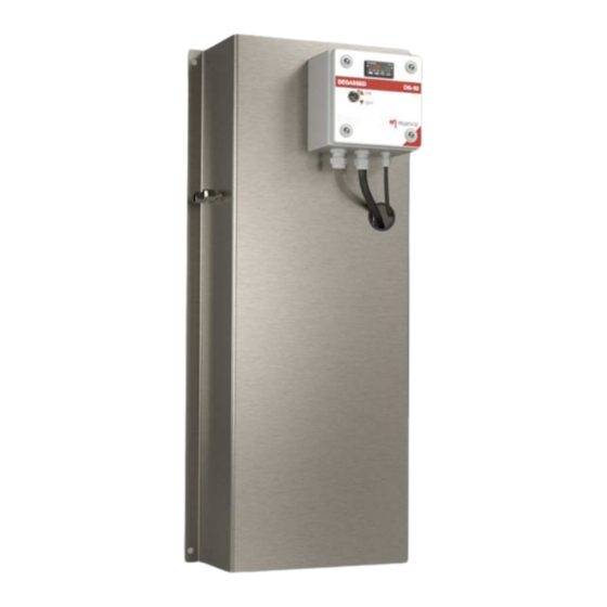
DEGASSING SYSTEM DG-50
INSTALLATION OPERATION & MAINTENANCE MANUAL
MANVIA SAMPLE DEGASSING SYSTEMS
INSTALLATION, OPERATION &
MAINTENANCE MANUAL
SAMPLE DEGASSING SYSTEM DG-50
MANVIA ESPAÑA
Camino Fontán Porceyo 590
33392 - Porceyo
Asturias - España
(+34) 984 20 45 49
analyzer@manvia.com
www.analyzersmanvia.com
Advertisement
Table of Contents

Related Manuals for manvia DG-50

Summary of Contents for manvia DG-50
- Page 1 DEGASSING SYSTEM DG-50 INSTALLATION OPERATION & MAINTENANCE MANUAL MANVIA SAMPLE DEGASSING SYSTEMS INSTALLATION, OPERATION & MAINTENANCE MANUAL SAMPLE DEGASSING SYSTEM DG-50 MANVIA ESPAÑA Camino Fontán Porceyo 590 33392 - Porceyo Asturias - España (+34) 984 20 45 49 analyzer@manvia.com www.analyzersmanvia.com...
-
Page 2: Table Of Contents
DEGASSING SYSTEM DG-50 INSTALLATION OPERATION & MAINTENANCE MANUAL INDEX Notes on Safety ............................3 APPLICATIONS ............................4 SPECIFICATIONS ............................4 GENERAL DESCRIPTION ..........................5 INSTALLATION ............................9 Mechanical ............................9 Process connections ........................10 Electrical connections ........................12 START UP ............................... 13 OPERATION ............................15 PROGRAMMING ............................ 15 Temperature set point adjusting .................... -
Page 3: Notes On Safety
Do not attempt to repair, disassemble, or modify DG-50 sample degassing CAUTION system, MANVIA is not responsible for any damages resulting from repairs, disassembly, or modification by unauthorized personnel. -
Page 4: Applications
INSTALLATION OPERATION & MAINTENANCE MANUAL 1 APPLICATIONS MANVIA DG-50 System offers a new design for conductivity measurement for water-steam cycle chemistry monitoring. This system ensures an effective CO₂ removal from sample and an appropriate temperature conditioning for an accurate degassed conductivity measurement. -
Page 5: General Description
DEGASSING SYSTEM DG-50 INSTALLATION OPERATION & MAINTENANCE MANUAL 3 GENERAL DESCRIPTION The objective of the degassing system is to raise the temperature of the sample to its boiling point, in order to remove the greatest amount of CO₂ from it. To maximize the extraction efficiency of CO₂... - Page 6 DEGASSING SYSTEM DG-50 INSTALLATION OPERATION & MAINTENANCE MANUAL Heat exchanger Heating cartridge The option of self-cooling, guarantees great stability to the system in the event of disturbances in the flow or temperature of the sample, as well as, not requiring a consumption of cooling water and the installation required for cooling water supply.
- Page 7 DEGASSING SYSTEM DG-50 INSTALLATION OPERATION & MAINTENANCE MANUAL 150mm Elevation from DG Inlet SAMPLE IN. NOT INCLUDED 1/4" NPT VACUUM BREAK DRAIN 140 mm Recommended height for VACUUM BREAK installation SAMPLE OUT 1/4" NPT CCD Measurement Ø 10 NOTE: TAKE INTO ACCOUNT...
- Page 8 DEGASSING SYSTEM DG-50 INSTALLATION OPERATION & MAINTENANCE MANUAL 150mm Elevation from DG Inlet SAMPLE IN. NOT INCLUDED 1/4" NPT VACUUM BREAK DRAIN 140 mm Recommended height for VACUUM BREAK installation SAMPLE OUT 1/4" NPT CCD Measurement COOLING W. 1/4" NPT Ø...
-
Page 9: Installation
DEGASSING SYSTEM DG-50 INSTALLATION OPERATION & MAINTENANCE MANUAL 4 INSTALLATION CAUTION: THE NECESSARY PROTECTIVE EQUIPMENT MUST BE USED IN ORDER TO AVOID KNOCKS, CUTS AND ENTRAPMENTS DURING INSTALLATION. FOLLOW THIS PROCEDURE FOR CORRECT INSTALLATION. 4.1 Mechanical This device must be located avoiding vibrations and direct exposition to sunlight. The system incorporates four holes in the four corners of degassing system panel, in order to fix it to a vertical wall. -
Page 10: Process Connections
DEGASSING SYSTEM DG-50 INSTALLATION OPERATION & MAINTENANCE MANUAL 4.2 Process connections Depending on the degassing system option chosen, process connections may vary in number and type, according to the next chart: CONNECTION DG50-0-C DG50-0-D DG50-1-C DG50-1-D DESCRIPTION SAMPLE INLET 1/4“ NPTF 1/4“... - Page 11 DEGASSING SYSTEM DG-50 INSTALLATION OPERATION & MAINTENANCE MANUAL Sample inlet and outlet connections • It is advisable, the use of corrosion resistant pipework, suitable for the fluid being sampled, in order to connect degasser system, to sampling stream. • Keep the length of tubing to a minimum. Only 80 mm of straight tube, must be respected from connection fitting (¼”...
-
Page 12: Electrical Connections
DEGASSING SYSTEM DG-50 INSTALLATION OPERATION & MAINTENANCE MANUAL 4.3 Electrical connections CAUTION: IT WILL BE NECESSARY TO VERIFY THAT THERE IS NO VOLTAGE IN POWER SUPPLY CABLE BEFORE TO START ELECTRIC WIRING. FOLLOW THIS PROCEDURE FOR CORRECT INSTALLATION: Power supply connection Degassing system, must be electrically supplied by connecting power supply cable to terminals X0. -
Page 13: Start Up
DEGASSING SYSTEM DG-50 INSTALLATION OPERATION & MAINTENANCE MANUAL Degassing system electric wiring diagram 5 START UP DANGER: TO AVOID THE RISK OF BURNS, IT IS ESSENTIAL BEFORE START-UP, VERIFY THAT IS NOT POSSIBLE TO ACCESS THE REAR PART OF THE MOUNTING PLATE. IF INSTALLED AS SPECIFIED IN THIS MANUAL, THERE IS NO RISK FOR ACCIDENTAL CONTACT WITH HOT PARTS. - Page 14 DEGASSING SYSTEM DG-50 INSTALLATION OPERATION & MAINTENANCE MANUAL CAUTION: BEFORE TO START-UP THE SYSTEM, IT MUST BE VERIFIED THAT THERE IS SAMPLE FLOW, FLOWING AT THE SAMPLE OUTLET. IF NOT, HEATER MAY BE DAMAGED BY INTERNAL OVERHEATING. • Switch on the circuit breaker (Q1) inside the electrical box to start up the equipment and close the electrical box.
-
Page 15: Operation
DEGASSING SYSTEM DG-50 INSTALLATION OPERATION & MAINTENANCE MANUAL 6 OPERATION Main operation display is shown when controller is energized and looks like appears bellow: The parameters shown in figure above are: 1. These digits, indicate temperature measured inside boiler in the selected temperature units, if system is stabilized, that will be the boiling point of water in this moment. -
Page 16: Temperature Set Point Adjusting
DEGASSING SYSTEM DG-50 INSTALLATION OPERATION & MAINTENANCE MANUAL 7.1 Temperature set point adjusting There are only two parameters which is mandatory to adjust, before to start-up the system, these parameter is temperature set point, and must be adjusted according to next procedure: •... - Page 17 DEGASSING SYSTEM DG-50 INSTALLATION OPERATION & MAINTENANCE MANUAL Boiling Boiling Boiling Boiling Boiling Boiling Altitude Altitude Altitude temperature temperature temperature temperature temperature temperature meters °C °F meters °C °F meters °C °F 212,0 201,2 86,1 187,0 1800 4150 99,8 211,6...
-
Page 18: Pid Control Parameters Adjusting
DEGASSING SYSTEM DG-50 INSTALLATION OPERATION & MAINTENANCE MANUAL • To adjust temperature set point, follow the next steps: Push enter key an hold for three seconds and the next menu appears: Then push index key two times and next display appears: By pressing down arrow key or up arrow key, is possible to change temperature set point the required value. -
Page 19: Maintenance
• Finally, to return to operation main display, press enter key. DANGER: MANVIA IS NOT RESPONSIBLE FOR ANY PROGRAMMING CHANGE NOT DESCRIBED IN THIS MANUAL, NEITHER FOR ANY PID CONTROL PARAMETERS CHANGE WHAT ARE WORKSHOP ADJUSTED. -
Page 20: Standard Warranty
MV-PT105 8.3 Standard warranty MANVIA warrants products manufactured and supplied by it, to be free from defects in workmanship and, to the extent materials are selected by Seller, to be free from defects in materials, for a period of twelve months from shipment. - Page 21 DEGASSING SYSTEM DG-50 INSTALLATION OPERATION & MAINTENANCE MANUAL MANVIA ESPAÑA Camino Fontán Porceyo 590 33211 - Porceyo Asturias - España (+34) 984 20 45 49 analyzer@manvia.com MA-DG-50r01...
Need help?
Do you have a question about the DG-50 and is the answer not in the manual?
Questions and answers