Table of Contents

Subscribe to Our Youtube Channel
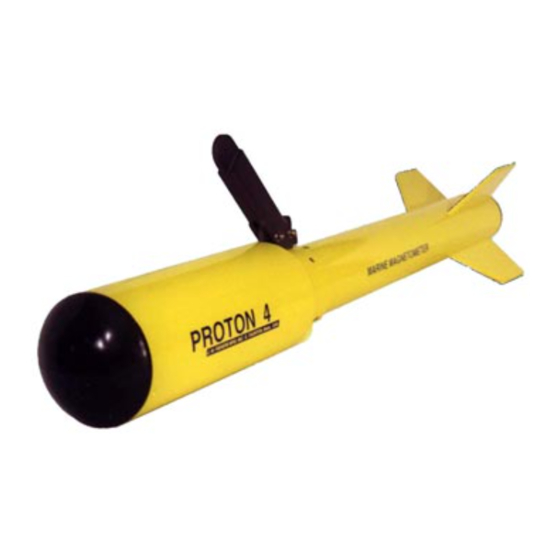
Related Manuals for JW Fishers PROTON 4


Summary of Contents for JW Fishers PROTON 4
- Page 1 PROTON 4 MARINE MAGNETOMETER REV 0609 OPERATION AND MAINTENANCE MANUAL JW FISHERS MFG INC 1953 COUNTY ST. E. TAUNTON, MA 02718 USA (508) 822-7330; (800) 822-4744; FAX (508) 880-8949 Email: jwfishers@aol.com WEB: www.jwfishers.com...
- Page 2 PROTON 4 MARINE MAGNETOMETER OPERATION MAINTENANCE MANUAL PROTON 4 MARINE MAGNETOMETER JW FISHERS MFG INC 1953 COUNTY ST. E. TAUNTON, MA 02718 USA (508) 822-7330; (800) 822-4744; FAX (508) 880-8949 Email: jwfishers@aol.com WEB: www.jwfishers.com...
-
Page 3: Table Of Contents
TABLE OF CONTENTS • DO'S AND DON'T ..........................4 • SPECIFICATIONS ..........................5 • DETECTION RANGES ........................6 • MAGNETIC DEVIATION CHART ...................... 7 • INTRODUCTION TO MAGNETOMETERS ..................8 • THEORY OF OPERATION ........................ 9 • SYSTEM BREAKDOWN ......................... 10 •... - Page 4 • Use #12 wire (or larger) to extend battery cable if needed. • If you are using the UA2 altimeter, be sure the sync cable from the Proton 4 control box is connected to the back of the UA2. If the UA2 is allowed to free-run it will interfere with the Proton 4 readout (readout jumps around).
-
Page 5: Specifications
PROTON 4 SPECIFICATIONS DIMENSIONS/WEIGHT: • Fish ............52' L x 6" Dia ............48 lbs • Control Box ........... 13"Lx13"Wx6"H ............5 lbs • Tow Line ..........75"Dx150/300' ........... 30/60 lbs • Carrying case ........53"Lx15"Dx13"H ............25 lbs • Total Shipping ........53"Lx15"Dx13"H ..........120/150 lbs PERFORMANCE/DESCRIPTION: •... - Page 6 CHART (above) EXAMPLE: As the Proton 4 fish approaches a small plane, you can expect a one gamma change at 65-75' (the digital readout would change one digit, ie: from 48,240 to 48,239). At 50' distance, another one gamma change would take place (ie: 48,238 on readout).
-
Page 7: Magnetic Deviation Chart
MAGNETIC DEVIATION CHART: (continued) The chart below shows that a 37 ton iron target will produce a 20 g change approximately 45 m away (146 feet). The grid lines were set up 90 m apart. If the target had not been found, the search pattern would have been repeated except the grid lines (boat passes) would have been in-between the original grid lines. - Page 8 PROTON 4 MAGNETOMETER INTRODUCTION The PROTON 4 Magnetometer is a precision electronic instrument that measures the strength of the earth's magnetic field. Once the magnetometer is set up in an area, it will inform the operator of the strength of the earth's magnetic field in that area (in gammas).
-
Page 9: Theory Of Operation
THEORY OF OPERATION The sensor, in the Fish, contains charcoal lighter fluid (ships empty from factory, see page 25) which is rich in protons (nuclei of hydrogen atoms). The protons act like small bar magnets and align themselves parallel to the earth's magnetic field (like a compass). -
Page 10: System Breakdown
SYSTEM BREAKDOWN The PROTON 4 is a Proton Magnetometer which consists of a FISH, TOW LINE, and CONTROL BOX. 150'/300' TOW LINE CONTROL BOX PROTON 4 FISH FISH - The FISH is made up of a 30" long 4" PVC tube and a 20" long 6" PVC tube. The 6" tube is filled for ballast and to isolate the sensor head (Proton Bottle) from salt water. - Page 11 TOW LINE - The 150' (300'/500'/1000' options are available) Tow Line consists of a multi-paired cable and coax which is the core of a braided polypropylene line. The combination results in a highly abration-resistant tow line. One end of the Tow Line is wired into the Fish, and the other end plugs into the Control Box.
- Page 12 CABLE PROTON 3 PRINTER In addition to the logic board, the Control Box contains switches and indicators on the front panel. Readout POL Time PROTON 4 Printer Alarm Power ONLED Power Switch Sensitivity POWER SWITCH - When turned on, the 24 volts from the boat/car battery feeds the Power Supply section on the Analog board.
- Page 13 UA2 SYNC PLUG - If a UA2 altimeter option is installed on the Proton 4, a cable must connected between the UA2 and the Proton 4 control box. This cable enables the UA2 to operate with the Proton 4 without causing interference (Readout jumping around) to the Proton 4.
- Page 14 The Altimeter's readout shows the distance in feet. See Altimeters manual for operating instructions. LORAN C/GPS - When a Loran C or GPS interface cable is plugged into the Proton 4 Control Box the printer will print out the position coordinates. The position coordinates will also be sent to the optional RS232 computer interface, if equipped.
-
Page 15: Operation
Do not operate the unit until the sensor housing is filled with charcoal lighter fluid. Operation of the Proton 4 is extremely simple. It will operate month after month without any adjustments once the unit is tuned. Once you have tuned for an area, if you change areas (more than 1,500 gammas), the unit should be checked for proper tuning before going out on the boat (always tune the unit on land, whenever possible, before heading for water). - Page 16 Put the sensitivity switch in the G1 position. This is the most sensitive position, the position you would like to normally operate the Proton 4. However, due to outside electrical noise, when the unit is out of the water, you may not be able to operate in this position.
- Page 17 Note: on land, even a properly tuned fish will not provide a steady readout if it is in an electrically noisy area. The Proton 4 fish is tuned by a switch located in the preamp housing in the rear of the fish. To gain access to the preamp housing the tail section of the fish must be removed (four screws).
-
Page 18: Tuning
PROTON 4 FISH TUNING 9-20-00 10 POSITION TUNING SWITCH 10 POSITION TUNING SWITCH 8 9 10 9 10 GAMMA'S GAMMA'S (FROM MAP) (FROM MAP) 67,000 ......1 45,000 ... 0 66,500 ......0 44,500 ... 0 66,000 ......1 44,000 ... 0 65,500 ...... -
Page 19: Field Use
FIELD USE READOUT INTERPRETATION: The key to successful magging is interpretation of the READOUT. If you follow the recommendations below, you will become an expert at it very quickly. 1. Practice on land - have a friend walk (slowly) by the Head carrying different size metal objects and at different distances from the Head. - Page 20 (put in plastic bag). If you are using the UA2 altimeter, be sure the sync cable from the Proton 4 control box is connected to the back of the UA2. If the UA2 is allowed to free-run it will interfere with the Proton 4 readout (readout jumps around).
-
Page 21: Shallow Water Towing
SHALLOW WATER TOWING: In shallow water towing, our goal is keeping the Fish off the bottom. This can be done quite easily by suspending the Fish from a float. The length of the line between the float and the Fish determines Fish depth. -
Page 22: Search Pattern
SEARCH PATTERN In most cases, the quickest and most efficient way to locate the wreck is to do your homework before going out. Once you have pinned the location down (as best you can) on a map, divide the area on the map into square blocks approximately one mile on each side (if a small amount of ferrous metal is involved, a few cannons, reduce the sides to 1/4 mile or less). - Page 23 LARGE OBJECTS: (small and large changes that last for many cycles). Drop buoy #1 (for a straight line reference) as soon as you start getting readings. Continue at same heading; when you lose target on mag, drop buoy #2. Swing boat around and make another pass in the opposite direction. You should pick up the target once again.
-
Page 24: Procedures (Filling Sensor Housing, Disassembly, Adjustments, Map Instructions)
PROCEDURES The following is a list of procedures that may be required for operation, adjustments, or maintenance: PROCEDURE DESCRIPTION Filling sensor housing with charcoal lighter fluid. P1.1 Nose cone removal. Loran C and GPS cabling. System checkout - From inside of a building. Fish tail section removal. - Page 25 1/4 turn will seal the housing. Use a paper towel to clean up any left over fluid around the bolt heads. 9. Reinstall the fish nose cone (see P1.1 next page). Proton 4 - Nose End View End of Sensor Housing...
- Page 26 6 decimal place precision. The information sent from the GPS or LORAN must include either the GLL or GGA sentence with no more than 6 decimal place precision. The GPS or LORAN connects to a 5 pin DIN connector on the the Proton 4 control panel. Two interface cables are supplied.
- Page 27 TAIL SECTION REMOVAL REMOVAL 1. Position the fish on a flat surface. Cable Tail Section PROTON 4 DO NOT REMOVE (4) REMOVE (4) REAR SCREWS FRONT SCREWS 2.
- Page 28 MAP INSTRUCTIONS The purpose of the world map is to inform you of the normal gamma reading in your area. This information is necessary for tuning the Fish so it will operate in your area. The map shows the strength of the earth's magnetic field in your area listed in gammas (purple lines).
- Page 29 24 VOLT BATTERY HOOKUP The Proton 4 requires 24 vdc to power the system. This is accomplished by wiring two 12 volt car or marine batteries in series (see below). Caution: Failure to properly connect batteries could damage the Proton 4 control box, batteries, and power cable.
- Page 30 TOW LINE REPLACEMENT The tow line for the Proton 4 consists of a coax and multi-paired cable which is fed through a hollow core polypropylene rope. NOTE: The rope at some point may have lumps or open areas. This is caused by manufacturing splices of individual strands within the rope.
- Page 31 4. Unsolder wires from board. 5. While holding the head of the feed-through connectors with your fingers, loosen the nuts (with a wrench) from the faceplate. REPLACEMENT 1. Install new cables by reversing above procedures. NOTE: Be sure o-rings are in place on the feed-through connectors and on the case (large o- ring).
- Page 32 Should it be necessary to replace the Pre-Amp board, perform these steps below. 1. Remove the tail section from the fish (see P4). Cable Preamp Housing PROTON 4 Interconnecting Tubing remove (4) screws from front faceplate 2. Remove the four screws from the front faceplate of the preamp housing. See P5.
- Page 33 PROTON 4 PRESSURE TEST PROCEDURE 1. Remove the tail section. See diagram. a. Position the fish on a flat surface. b. Remove the four rear screws from the tow collar that hold the tail section in place (note that the hole and slot are on the top side of the tail section).
- Page 34 RS232 COMPUTER INTERFACE CABLING The Proton 4 can be connected to any computer or data recorder equipped with an RS232 input. The specification for the interface is as follows: • 8 bit ASCII • 4800 baud rate • 1 stop bit •...
- Page 35 The message repeats once for each cycle of the magnetometer. The RS232 interface uses two wires and is wired to the modified three pin DIN connector (CENTER PIN CUTOFF) on the PROTON 4 as follows: RS232 Interface 9 pin "D" female To 5 pin conn.
-
Page 36: Troubleshooting
2) Damaged cable connector (where fish cable plugs into control box). 3) Bad preamp in fish. PROBLEM #2 Proton 4 stops cycling - One or both 12 volt batteries need recharged. CALL FACTORY IF ANY PROBLEMS 800-822-4744 ph 508-822-7330 ph 508-880-8949 fax jwfishers@aol.com... -
Page 37: Warranty
LIMITED WARRANTY The Warranty on the Proton 4 is for two years from date of purchase and is limited to the electronic portion of the unit. The Warranty does not include broken or damaged tow line or lost equipment. Should service be required, contact us explaining the nature of the problem.
Need help?
Do you have a question about the PROTON 4 and is the answer not in the manual?
Questions and answers