
Related Manuals for Morso F

Summary of Contents for Morso F
- Page 1 Instruction Manual MORSØ Mitring Machine Model F Instruction Manual MORSØ Mitring Machine Model F...
-
Page 2: Table Of Contents
F-1 Changing of Knives page F-2 Grinding of Knives page F-3 Regulation of Draw Bar page F-4 Adjustment of Forward Movement page F-4 Adjustment of Springs page F-5 Adjustment of Height Movement page F-6 Changing of Spare Parts page F-7... -
Page 3: Introduction
Instruction Manual MORSØ Mitring Machine Model F Introduction Introduction We recommend that you read this instruction manual thoroughly before using this machine. Damage or faults on the machine caused by misuse or incorrect operation are not covered under our conditions of warranty. -
Page 4: Functional Description
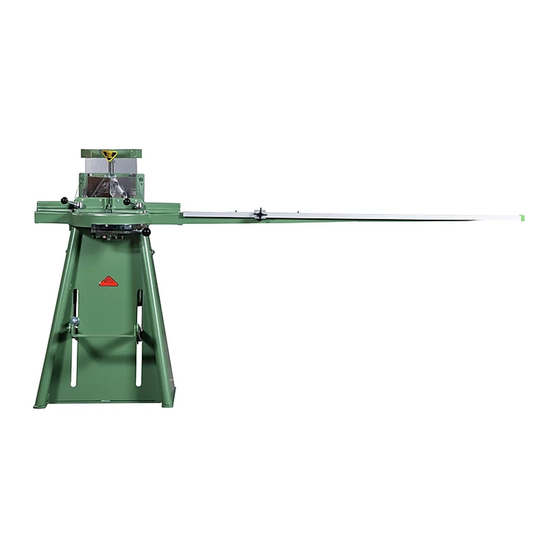
45 degrees through to 90 degrees on either side of the knife block, plus adjustable rebate supports. MORSØ-F cuts a double mitre at 45 degrees and a single mitre up to 90 degrees. MORSØ-F allows you to achieve a perfectly smooth, clean, and accurate finish, by nibbling the work piece in two cuts. -
Page 5: Overview
Instruction Manual MORSØ Mitring Machine Model F Functional Description Overview... - Page 6 Instruction Manual MORSØ Mitring Machine Model F Functional Description Overview Pos. Designation Pos. Designation Pos. Designation Frame Hand Lever, Fence, Foot Pedal right hand Machine Table Foot Pedal Tipper Table Extension Scale in Degrees, Fence, Lock Nut * left hand...
-
Page 7: Machine Description
Instruction Manual MORSØ Mitring Machine Model F Functional Description Machine Description... - Page 8 Model F Functional Description Machine Description The MORSØ-F is constructed as a compact machine with a sturdy frame (1) and built in lever system (46) (not shown). The cutting assembly is situated on top of the machine. The knife block (4) slides up and down in the slide frame (10) fitted at the cross (11), and forwards and rearwards in the guides (12) and a cross guide in the table (2).
-
Page 9: Description Of The Lever Linkage System
Instruction Manual MORSØ Mitring Machine Model F Functional Description Description of the Lever System... - Page 10 The vertical length of the stroke of the knives is adjusted at the factory to 165 mm, but this can be re-adjusted to max. 200 mm, if necessary, (see chapter F-6). The cutting action is achieved by a foot operated lever mechanism.
-
Page 11: Cutting Method
Instruction Manual MORSØ Mitring Machine Model F Functional Description Cutting Method... - Page 12 Instruction Manual MORSØ Mitring Machine Model F Functional Description Cutting Method Prior to operation, the knife block (4) is in its topmost position and the sliding frame (10) in its rearmost position. If the moulding to be cut has a rebate, the rebate supports (31) are adjusted to the required height.
-
Page 13: Technical Data
Working Width (max.) * 100 mm Distance to Wall min.1000 mm Working Height (max.)* 145 mm Noise/Pollution: Square Cutting (max.) 65/65 mm Noise Level silent Measuring Scale (up to) 1,500 mm Pollution nil/no dust *see diagram, page C-2 and service F-6... -
Page 14: Dimensions Of Work Pieces
On the right (vertical) measuring scale the height can be read, and on the horizontal measuring scale the width can be read. Please Note: The factory preset the cutting height to 145 mm as standard. Should you require a max. cutting height of 185 mm. Please see Service, page F-6. -
Page 15: Assembly Instructions
Instruction Manual MORSØ Mitring Machine Model F Assembly Instructions In General... - Page 16 Instruction Manual MORSØ Mitring Machine Model F Assembly Instructions In General The machine is delivered assembled ready for use, except for the table extension (3) and divided beam (26) which are disassembled during transit. The machine comes complete with all standard equipment.
-
Page 17: Operating Instructions
Instruction Manual MORSØ Mitring Machine Model F Operating Instructions E-1 Operating Devices... - Page 18 Instruction Manual MORSØ Mitring Machine Model F Operating Instructions E-1 Operating Devices 19 = Handle - secures the left hand fence 24 = Star Wheel – tightens, to secure the 21 = Scale – in degrees measurements stop. for adjustment of left hand fence 26 = Scale (Rule) –...
-
Page 19: Before Operating
Instruction Manual MORSØ Mitring Machine Model F Operating Instructions E-2 Before Operating... - Page 20 Instruction Manual MORSØ Mitring Machine Model F Operating Instructions E-2 Before Operating Before operating the machine the following must be checked and adjusted: Check a) Knives (5) General condition Sharpness b) Waste Room for waste cuttings c) Safety devices Fitting of all safety devices:...
- Page 21 Instruction Manual MORSØ Mitring Machine Model F Operating Instructions E-3 Degree Adjustment of Fences - Exact Adjustment of the Fences E-3-1 E-3-2...
-
Page 22: Degree Adjustment Of Fences
Instruction Manual MORSØ Mitring Machine Model F Operating Instructions E-3 Degree Adjustment of Fences (Fig. E-3-1) The fences (17) + (18) can be adjusted as required (from the factory they are adjusted to 45° for a double mitre). If, for instance, you want to make a 6-sided (hexagonal) frame the following procedure is used: 6 pieces of moulding are cut in the normal way at 45°... -
Page 23: Adjustment Of Length Of Moulding
Instruction Manual MORSØ Mitring Machine Model F Operating Instructions E-4 Adjustment of Length of Moulding... - Page 24 Instruction Manual MORSØ Mitring Machine Model F Operating Instructions E-4 Adjustment of Length of Moulding Principle: The inside measurement of a frame = outside measurement less 2 times the width of the moulding – excluding the width of the rebate (if both ends are cut at 45°.) The width of the moulding is measured by means of the measuring scale (a) on the table extension (3).
- Page 25 Instruction Manual MORSØ Mitring Machine Model F Operating Instructions E-4-1 Measuring Scale De-Luxe E-4-1...
- Page 26 Instruction Manual MORSØ Mitring Machine Model F Operating Instructions E-4-1 Measuring Scale De-Luxe Principle: The measuring scale engraved in the table indicates the distance from the right knife in inches. E.G. the line marked 8 has a distance of 8 inches from the right knife.
- Page 27 Instruction Manual MORSØ Mitring Machine Model F Operating Instructions Adjustment of Rebate Supports - Adjustment of the Forward Movement E-5-1 E-5-2...
-
Page 28: Adjustment Of Rebate Supports
Instruction Manual MORSØ Mitring Machine Model F Operating Instructions Adjustment of Rebate Supports (Fig. E-5-1) The knife block must be in the topmost position during the adjustment. The rebate supports are only used when cutting mouldings with rebates. To adjust the rebate supports knurled lock-nut (32) is loosened. -
Page 29: Adjustment Of Height Stop
Instruction Manual MORSØ Mitring Machine Model F Operating Instructions E-6 Adjustment of Height Stop... - Page 30 Instruction Manual MORSØ Mitring Machine Model F Operating Instructions E-6 Adjustment of Height Stop The height stop (41) is used for adjustment of the knife block (4) to a suitable height comparable with the moulding to be cut. This avoids unnecessarily high foot movements.
-
Page 31: Working Procedure
Instruction Manual MORSØ Mitring Machine Model F Operating Instructions E-7 Working Procedure... - Page 32 Instruction Manual MORSØ Mitring Machine Model F Operating Instructions E-7 Working Procedure The right hand side of the moulding is trimmed to 45°. Place the knife unit (a) must in the rearmost position and the knife block (4) in the topmost position.
-
Page 33: Lubrication Instructions
Instruction Manual MORSØ Mitring Machine Model F Service Lubrication Instructions... -
Page 34: Cleaning
5. All the linkages in the lever system (46), incl. spring suspension. Lubricant: Any acid-free oil. Cleaning MORSØ-F must be cleaned thoroughly after use. Remove any waste wood from all the guides. (a ½” paint brush is ideal for this) Remove the waste from the rebate support guides. -
Page 35: Changing Of Knives
Instruction Manual MORSØ Mitring Machine Model F Service Changing Knives... - Page 36 Instruction Manual MORSØ Mitring Machine Model F Service Changing Knives When the cutting is no longer satisfactory, e.g. unclean cut surfaces with grooves, the knives must be changed or sharpened. Precautions recommended: Place a block of wood 2 mm below the knives so they cannot drop.
-
Page 37: Grinding Of Knives
Instruction Manual MORSØ Mitring Machine Model F Service Grinding of Knives... - Page 38 Even the slightest error here will cause the knife to press too hard against the wood during the cutting, causing damage or bruising to the moulding. Please also see page F-4: Regulation of Draw Bar...
- Page 39 Instruction Manual MORSØ Mitring Machine Model F Service Regulation of Draw Bar / Adjustment of Forward Movement F-4-1 F-4-2 F-4-3...
-
Page 40: Regulation Of Draw Bar
When you have replaced the knives it might be necessary to adjust the forward travel to ensure that the rear of the moulding is cut through (picture F-4-3). 1. The knife block unit is placed in the front most position with lever (13) (in the picture it is shown in the rear position). - Page 41 Instruction Manual MORSØ Mitring Machine Model F Service Adjustment of the Return Springs...
- Page 42 Instruction Manual MORSØ Mitring Machine Model F Service Adjustment of the Return Springs The return springs (42) which return the knife block (4) to the topmost position are attached to the spring anchors (43) located in the bottom holes in the sides of the main frame.
-
Page 43: Adjustment Of Height Movement
Instruction Manual MORSØ Mitring Machine Model F Service Adjustment of Height Movement... - Page 44 5. Fasten the draw bow holders (39) in the draw bow (38) again. 6. Place the springs (42) in the spring anchors (43) and the draw bow holders (39). 7. The draw bar (40) is adjusted as described under F-4.
-
Page 45: Changing Of Spare Parts
Instruction Manual MORSØ Mitring Machine Model F Service Changing of Spare Parts... - Page 46 Instruction Manual MORSØ Mitring Machine Model F Service Changing of Spare Parts If it is necessary to change worn out or damaged parts we recommend that you proceed in the following manner: 1. The index of the spare parts list (see page I-1) refers to which specific list the spare part can be located.
-
Page 47: Rectifying Faults
Model F Rectifying Faults Faults Cause Repair Incorrect cuttings Blunt knives Replace knives / Resharpen See page F-2 Knives incorrectly installed Check the installation See page F-2 Moulding with rebate burrs Rebate supports incorrectly Correct the adjustment adjusted See page E-5... -
Page 48: Safety
Safety Safety Devices I M P O R T A N T According to current safety regulations MORSØ-F must not be used without the following safety devices: 1. Safety Guard (47) for knife block 2. Safety Guards (49) in the fences... - Page 49 Instruction Manual MORSØ Mitring Machine Model F NOTES...
-
Page 50: Index Of Spare Parts
Instruction Manual MORSØ Mitring Machine Model F Index of Spare Parts Oversigt - Index – Übersicht Pos. Betegnelse Designation Bezeichnung Side/Page/Seite Grundmaskine Basic Machine Grundmaschine Bord, komplet Table, complete Tisch, komplett Knivhovedenhed Knife Block Unit Messerkopf-Einheit Drivmekanisme Drive equipment Antriebsmechanik Falsstøtter... - Page 51 Instruction Manual MORSØ Mitring Machine Model F Index of Spare Parts Grundmaskine - Basic machine – Grundmaschine...
- Page 52 Instruction Manual MORSØ Mitring Machine Model F Index of Spare Parts Grundmaskine - Basic Machine - Grundmaschine Pos. Art. No. Betegnelse Designation Bezeichnung 30000326 Stativ Frame Gestell 80372224 Skive Washer Scheibe 80382223 Skrue Screw Schraube 01602222 Højdestop Height stop Höhenbegrenzung...
- Page 53 Instruction Manual MORSØ Mitring Machine Model F Index of Spare Parts Bord, komplet – Table, complete – Tisch, komplett...
- Page 54 Instruction Manual MORSØ Mitring Machine Model F Index of Spare Parts Bord komplet – Table, complete – Tisch, komplett Art. Nr. Betegnelse Designation Bezeichnung 20000120 Bord Table Tisch 20000064 Styreliste Short Guide Rail Steuerleiste 13504004 Håndtag, komplet Hand Lever, complete...
- Page 55 Instruction Manual MORSØ Mitring Machine Model F Index of Spare Parts Knivhovedenhed - Knife Block Unit - Messerkopf-Einheit...
- Page 56 Instruction Manual MORSØ Mitring Machine Model F Index of Spare Parts Knivhovedenhed - Knife Block Unit - Messerkopf-Einheit Art. No. Betegnelse Designation Bezeichnung 00000130 Slæderamme Slide Frame Schlittenrahmen 20000140 Knivhoved Knife Block Messerkopf 20000160 Kryds Cross Kreuzstück 26500050H Styreliste Long Guide Rail...
- Page 57 Instruction Manual MORSØ Mitring Machine Model F Index of Spare Parts Drivmekanisme - Drive Equipment - Antriebsmechanik...
- Page 58 Instruction Manual MORSØ Mitring Machine Model F Index of Spare Parts Drivmekanisme - Drive Equipment - Antriebsmechanik Art. No. Betegnelse Designation Bezeichnung 00000217 Fodvipper Foot pedal tipper Fuβhebel 01000070 Pedal Pedal Pedal 01102121 Aksel Shaft Achse 00000219 Trækbøjle komplet Draw bow, complete Zugbügel, komplett...
- Page 59 Instruction Manual MORSØ Mitring Machine Model F Index of Spare Parts Falsstøtter - Rebate Support - Falzauflagen...
- Page 60 Holder Halter 80233603 Rouletteret møtrik Knurled Nut Rändelmutter 80243703 Rouletteret møtrik Knurled Lock-nut Rändelmutter 12503903 Tap f. falsstøtte Pin f. rebate support Zapfen f. Falzauflagen 12203003V Underpart Bottom Part Unterteil 12203203V Vinkeljern Angle Iron Winkelstahl 50006020 Cylinderskrue Cylinder Screw Zylinderschraube 49004010 Undersænket skrue...
-
Page 61: Accessories
Instruction Manual MORSØ Mitring Machine Model F Accessories L-1-1 Automatic Rebate Support Attachment. The automatic rebate support attachment is available as an accessory. The automatic rebate support attachment is ideal for series production of frames. With this accessory, the rebate supports automatically return to the adjusted width after each cutting cycle. -
Page 62: Installation Instructions
Instruction Manual MORSØ Mitring Machine Model F Accessories L-1-2 Installation Instructions L-1-2 L-1-2-1... - Page 63 Instruction Manual MORSØ Mitring Machine Model F Accessories L-1-2 Installation Instructions Install the attachment on the left side first. 1. The knife block unit must be in the rearmost position and locked in the bottom position. Under no circumstances must the knife block be moved during the installation of the automatic rebate support system.
-
Page 64: Adjustment Of Rebate Supports
Instruction Manual MORSØ Mitring Machine Model F Accessories L-1-3 Adjustment of Rebate Supports L-1-3... - Page 65 Instruction Manual MORSØ Mitring Machine Model F Accessories L-1-3 Adjustment of Rebate Supports The knife block must be in the topmost position during the adjustment. The rebate supports are only used when cutting mouldings which have a rebate. To adjust the rebate support to the current work piece, the star wheel (8) and knurled lock nuts (32) are loosened.
-
Page 66: Index Of Spare Parts
Instruction Manual MORSØ Mitring Machine Model F Index of Spare Parts Ekstraudstyr Falsstøtter, autom. – Accessories- Automatic Rebate Supports. Zusatzausrüstung Falzauflagen, autom. - Page 67 Instruction Manual MORSØ Mitring Machine Model F Index of Spare Parts Ekstraudstyr Falsstøtter, autom. – Accessories- Automatic Rebate Supports. Zusatzausrüstung Falzauflagen, autom. Pos. Art. No. Betegnelse Designation Bezeichnung 05000121V Underpart Bottom Part Unterteil 05000125 Underlagsskive Washer Unterlegscheibe 05000123 Holder Holder...
Need help?
Do you have a question about the F and is the answer not in the manual?
Questions and answers