Table of Contents
Advertisement
Advertisement
Table of Contents

Summary of Contents for CryopAL TP-35
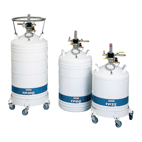
- Page 1 Self-pressurizing storage tanks TP 35 – TP 60 – TP 100 User’s manual...
- Page 2 Copyright 2017 by Cryopal Document code: NH78163 – English version Edition January 2017 – Revision I All rights reserved. This document may not be reproduced in any form whatsoever, in whole or in part, without written permission from Cryopal.
-
Page 3: Table Of Contents
Contents 10. Technical specifications ......... 34 About this manual ..........5 10.1 Tank ............34 1.1 Purpose of the manual ....... 5 10.2 Control head..........35 1.2 Who this manual is for ........ 5 1.3 Structure of the manual ......5 11. -
Page 5: About This Manual
The accompanying document contains: This manual in electronic pdf format. Topic Page Manuals issued by Cryopal. Overview of the TP tank Note: you will need to have the software known as Acrobat Reader installed on your computer to be Assembly (parts and options) able to read or print from this pdf manual in pdf format. -
Page 6: Safety
2. Safety service and protected against accidental usage. Full service and protected against accidental usage. Full Symbols used safety cannot be guaranteed in the following cases: safety cannot be guaranteed in the following cases: Symbol Meaning The equipment is visibly damaged. visibly damaged. -
Page 7: Precautions In The Event Of Operating Faults
2.2.2 Safe use of liquid nitrogen (operator equipped with all required cryogenic personal protection The temperature of liquid nitrogen is -196 °C. As a equipment: gloves, apron, visor, etc.) result: in order to avoid any liquid nitrogen splashing. You must never touch objects which The neck of the tank must never be have been in contact with liquid hermetically sealed. -
Page 8: Destruction Of The Unit
Destruction of the unit In order to protect the environment the equipment (the tank and its peripheral equipment) must be disposed of via the proper channels. -
Page 10: Components Supplied
3. Components supplied The product is delivered complete with: Ref. Designation Insulating stopper. ATP container (see table of capacities on page 34). Document containing this manual in pdf format. Figure 3-1: The delivered parts. -
Page 12: General
4. General Guide to components This illustration shows the main parts, both included ones and options that make up a storage tank in the TP product line. These are described in greater detail in the following paragraphs and pages. The tanks will be used in an appropriate environment. -
Page 14: Description
5. Description This section describes the two main parts, i.e. the Refer to: storage tank and the control head. On page 12 for details of how these components operate. On page 34 for the technical specifications of the Storage tank various models. -
Page 15: The Control Head
control head and the storage tank flange. The control head Refer to: The control head can provide a quick check of the amount of available liquid in the tank. It includes the On page 12 for details of how these components following withdrawal, level reading and safety devices: operate. - Page 16 5.3.3 Flexible transfer lines Cryopal flexible lines comply with the EN12434 standard. 5.3.3.1 Type 130/130 It is essential to ensure that a safety This flexible transfer line (or hose), which vary in valve calibrated to 15 bar maximum is length, is intended to fill the TP from a supply tank or inserted at one end of the flexible line vacuum line.
-
Page 18: Unpacking And Installation
6. Unpacking and installation Unpacking Installation checklist For your own safety you must observe the safety rules Action Yes, No, not and use suitable tools for unpacking and personal done done protection equipment. Check general At least two able people are needed to unpack the condition of the apparatus. - Page 19 Action Yes, No, not done done around the apparatus)? Is the liquid nitrogen supply pressure lower than bars? Has the medical apparatus been blown through (to eliminate traces moisture)?
-
Page 20: Installing The Components
7. Installing the components This section describes how to add various peripheral 4. Introduce the bottom of the control head (4) into devices (control head, castor base) to the storage the tank, taking care not to knock the neck of the tank. -
Page 21: Removing The Control Head
Removing the control head Proceed as follows: Check that there is no liquid nitrogen in the tank and it has been dried with dry air. 1. Open vent valve (2); Close filling/withdrawal valve (1). Close the pressure- building valve (3). Ensure that the vent valve (2) is open before doing anything else. -
Page 22: Use
8. Use This section introduces the use of the assembled tank If possible, use the optional dolly base. during transport, handling, filling (by gravity or from a Move the tank with the neck open. supply tank) and withdrawal (using the liquid nitrogen). - Page 23 3. Fit the filling valve's connector (5) onto the supply line by means of a transfer hose (130 TC or 130/130) (4). Figure 8-1: No person standing here during filling. To fill the tank, proceed as follows: Refer to the safety notes in section 8.4, on page To limit filling time, it important to use the shortest possible transfer line (1.1 or The tank must never be left unattended during...
-
Page 24: Withdrawal
7. As soon as liquid starts to issue from the vent flexible withdrawal line attached to the withdrawal valve (2), stop filling by closing the line (or supply valve. No additional equipment is needed. tank) valve. Proceed as follows: For details of this operation, refer to the instruction manual for the supply tanks. - Page 25 4. While holding the hose, gradually open the withdrawal valve (1) in order to start withdrawing while controlling the flow. Beware of possible splashes of nitrogen. The pressure reading on the pressure gauge must be 0.5 bars or lower. The top of the control head may become covered in frost during use.
-
Page 26: Maintenance
(see section 9.5.2, on of order gauge is operating properly page 31). (see section 9.3.1, on page Poor quality Contact your local Cryopal 27). Replace it if necessary vacuum, causing a representative. (see section 9.5.1, on page liquid 30). -
Page 27: Preventive Maintenance
Proceed as follows: 9.1.5 Uncontrolled service pressure 1. Close vent valve (2). Close Causes Corrective action filling/withdrawal valve (1). Close the pressure- Pressure controller Adjust the controller's service building valve (3). out of adjustment. pressure. Adjust the operating pressure on the controller by lifting the red locking ring of the controller and turning the knurled knob clockwise to... - Page 28 4. Lower the pressure in the tank slowly. To do so, close the fill valve (1) and gradually open the vent 6. If the difference between the readings is greater valve (2). than 0.1 bar, we recommend replacing the pressure gauge (7) (see section 9.5.1, on page 30).
-
Page 29: Adjusting The Level Indicator
2. Remove the control head. Refer to section 7.2, on page 21. 2. Using the brush, dab soapy water over the various connections. If bubbles appear, this indicates a 3. Once the assembly has warmed up to room leak. If a leak is observed, renew the seal on the temperature, check that the stem (2) slides connection concerned. -
Page 30: Changing Components
4. Place the ring (3) at the correct height and tighten the grub screw (4) again to immobilise the ring. Thus the more the spring is stretched (ring displaced towards the float) the higher the red mark rises (5). 3. Adjust the ring as shown in section 9.4.1. If the above actions do not allow the level to be adjusted, the spring must have been damaged by bad handling. -
Page 31: Interview Frequency
3. Apply PTFE tape or joint filler (silicone etc.) to the threads of the replacement part, taking care not to obstruct the orifices. 8. Test for leaks as described in section 9.3.4, on 4. Screw the part in, keeping tight control so as not to page 29. -
Page 34: Technical Specifications
10. Technical specifications 10.1 Tank Unit TP 35 TP 60 TP 100 Total capacity Litres Working capacity Litres Maximum working gauge pressure Static duration of use Days Weight when empty, without control head 17,6 Weight when empty, with control head 19,8 26,4 33,5... -
Page 35: Control Head
Figure 10-1: Dimensions (in mm). 10.2 Control head Feature Principal characteristics Nitrogen level: Measured by a mechanical level indicator (float) Nitrogen pressure Pressure gauge (graduated from 0 to 1.6 bar) Controller Integral Safety 2 valves calibrated to 0.5 bar Manual valves Filling / withdrawal Vent / overflow... -
Page 36: Spare Parts And Accessories
11. Spare parts and accessories 11.1 Tank Item Product references Pressure-building valve ACC-TP-6 Controller 0.07 - 0.7 bar ACC-TP-5 11.2 Control head Item Product references Full control head for TP35 ACC-ALU-6 Full control head for TP60 ACC-ALU-10 Full control head for TP100 ACC-ALU-11 Withdrawal valve / vent valve ACC-TP-7... -
Page 37: Accessories
11.3 Accessories Item Product references Elbow with anti-splash device ACC-TP-17 Anti-splash device ACC-ALU-12 Two-valve TP withdrawal assembly ACC-TP-21 TC withdrawal rod - FLEX DN10 180/180 NL ACC-FLTC-1 TC withdrawal rod + Anti-splash device ACC-FLTC-2 180/180 NL Hand rail Hand rail for TP35, TP60 and TP100 ACC-ALU-21 Hoses 130TC Flexible line for nitrogen, nom. -
Page 38: Warranty And Limit Of Liability
Goods are delivered at the vendor’s risk if delivered profit, loss of cryogenic liquid or of products in storage by a carrier appointed by Cryopal. In other cases etc. Within the limits imposed by applicable legislation, delivery is at the buyer’s risk. -
Page 40: Index
13. Index 130 TC, 15 ISE, 8 Leaks 130/130, 15 E-mail, 2 Inspection, 28 Equipment Level, 14 Destruction, 8 Level error, 25 Excess internal pressure, 14 Level indicator, 14 Accessories, 34 Inspection, 27 Control head, 33 Limit of liability, 35 Dolly base, 34 Hand rail, 34 Fault, 8... - Page 41 Operators, 7 Handling, 21 Valve:Overflow, 14 Safety valve, 14 Maintenance, 25 Valve:Pressure-building, 13 Shutoff valve, 11 Moving, 21 Valve:Venting, 14 Site web Cryopal, 2 Specifications, 31 Valve:Withdrawal, 14 Skimming, 5 Storage, 21 Spares Use, 23 Control head, 33 Withdrawal, 23...
Need help?
Do you have a question about the TP-35 and is the answer not in the manual?
Questions and answers