Advertisement
Quick Links
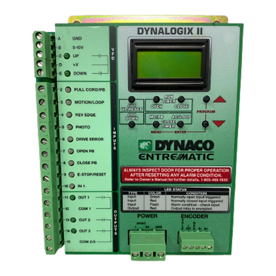
DYNACO USA, INC,
TECHNICAL MANUAL SUPPLEMENT
A
GND
B
0-10V
V
F
C
UP
D
D
+V
E
DOWN
2
PULL CORD/PB
3
MOTION/LOOP
4
REV EDGE
I
5
PHOTO
N
P
6
DRIVE ERROR
U
T
7
OPEN PB
S
8
CLOSE PB
9
E-STOP/RESET
10
IN 1
11
OUT 1
O
12
COM 1
U
T
P
13
OUT 2
U
T
14
OUT 3
S
15
COM 2/3
MESSAGE DISPLAY / COUNTER
RUN
TIMERS
JOG
OPEN
CLOSE
UP/RESET
JOG
MC/PB
AC/LOOP
DOWN
CLOSE
TIMERS
ENTER
MENU
DYNALOGIXII
ALWAYS INSPECT DOORS FOR PROPER OPERATION
AFTER RESETTING ANY ALARM CONDITION
REFER TO OWNERS MANUAL FOR FURTHER DETAILS. 1-800-459-1930
LED STATUS
TYPE
COLOR
INPUT
GREEN
NORMALLY OPEN INPUT TRIGGERED
INPUT
RED
NORMALLY CLOSED INPUT TRIGGERED
INPUT
FLASH
ALARM CONDITION - CHECK INPUT
OUTPUT
RED
OUTPUT RELAY IS ENERGIZED
POWER
ENCODER
24VAC
1
X2
GND
PROGRAM
CONDITION
S
H
G
L
+
N
D
12
D A- A+
S
B
G
W
R
H
H
L
R
E
L
T
K
N
D
D
The Leader in Door Safety & Design
Advertisement

Summary of Contents for DYNACO Dynalogix II
- Page 1 NORMALLY CLOSED INPUT TRIGGERED OUT 1 INPUT FLASH ALARM CONDITION - CHECK INPUT OUTPUT OUTPUT RELAY IS ENERGIZED COM 1 POWER ENCODER OUT 2 24VAC OUT 3 D A- A+ COM 2/3 The Leader in Door Safety & Design DYNACO USA, INC,...
- Page 2 INPUT FLASH ALARM CONDITION - CHECK INPUT OUTPUT OUTPUT RELAY IS ENERGIZED COM 1 POWER ENCODER OUT 2 24VAC OUT 3 D A- A+ COM 2/3 utputs Encoder Wire Connection The Leader in Door Safety & Design DYNACO USA, INC,...
- Page 3 MESSAGE DISPLAY / COUNTER DIFFERENT MESSAGES OF OPERATION READY SECOND LINE DISPLAYS CYCLE COUNTER / TIMER SETTINGS Figure 1.0-2: DY4000 display Note: Most error codes can be reset using the JOG UP/RESET button The Leader in Door Safety & Design DYNACO USA, INC,...
-
Page 4: Setting Limits
Setting Limits Confirm all electrical connections are properly wired and terminated before power up. STOP Reference: Wiring Diagram that came with DYNACO Door. Setting Limits on Initial Power-up Automatic activation's should be disconnected prior to setting limits. If connected door may activate and injury or damage may occur. - Page 5 Figure 2.0-4: Arrow Buttons (Scroll) 10. Press and release ENTER button. Display will change to:JogToPht_Enter. 11. Use the JOG UP/RESET button to bring door up one inch above the photo eyes. See figure 2.0-5. The Leader in Door Safety & Design DYNACO USA, INC,...
- Page 6 Setting/Adjusting Limits after Initial Power Up For first time users it is recommended not to use section 2.1. Please go back to STOP section 2.0 and go through the step by step procedure. The Leader in Door Safety & Design DYNACO USA, INC,...
- Page 7 9. Press and release the MENU button twice and the display changes to Ready. Note: Password number will be stored for 4 minute after entering it in. Entering program mode at this time will not require reentering of password number. The Leader in Door Safety & Design DYNACO USA, INC,...
- Page 8 These timers should be set for a period that exceeds the duration of a full open or close cycle. 1. Press and release Open Run Timer button on the Dynalogix II controller. The display will change to: Opening_Time=##. See figure 3.0-1.
- Page 9 Manual & Automatic Close Timers Setting the Manual & Automatic Close Timers The Dynalogix II has two automatic close timers. The first timer, MC/PB timer, will count down after a activation is installed on terminal number 2 (most commonly used for pull cords or pushbuttons). MC/PB timer also can be turned on or off, making it manual operation or automatic operation simply by assigning a countdown value to the timer.
- Page 10 Note: If value is set to zero, the timer is deactivated and the activations put on terminal number 2 is now in manual operation. Setting AC/LOOP Timer 1. Press and release AC/LOOP timer button on the Dynalogix II controller. The display will change to: AC Delay_Timer=##. See figure 4.2-1. AC/LOOP...
- Page 11 For example; a pull cord is wired to terminal 2 on the Dynalogix II, when you pull the cord, it sends a signal to the Dynalogix II. The Dynalogix II knows what the signal is do to the assigned input (terminal 2) the signal is coming through on.
- Page 12 Input 9: Used for emergency stop or to stop door from being activated. Also can be wired as the stop button in a three position switch. Input 10: Used by DYNACO USA Inc. for optional operations ordered with Dynaco door.
Need help?
Do you have a question about the Dynalogix II and is the answer not in the manual?
Questions and answers