Table of Contents
Advertisement
Quick Links
Advertisement
Table of Contents

Summary of Contents for enertik 100A
- Page 1 Motive Charger User Manual Version: 1.1...
-
Page 2: Table Of Contents
Table of Contents SAFETY INSTRUCTIONS .......................... 1 INSTALLATION ............................2 Unpacking and Inspection ........................2 Product Overview ..........................2 Mounting the Unit ..........................3 AC Input Connection .......................... 4 Battery Connection ..........................5 OPERATION ............................... 7 Power ON/OFF ........................... 7 Operation and Display Panel ...................... -
Page 3: Safety Instructions
1. SAFETY INSTRUCTIONS Thanks for choosing our product, please read carefully the following user manual and the safety instructions before installing the unit or using the unit! Keep this manual for future reference. CAUTION – The batteries should be match with the voltage and current of this product to operate ... -
Page 4: Installation
2. INSTALLATION Unpacking and Inspection Before installation, please inspect the unit. Be sure that nothing inside the package is damaged. You should have received the following items inside of package: Charger Unit Manual Mounting bracket x 2 M5 screws x 3 M10 expansion bolts x 4 U bracket DC cable... -
Page 5: Mounting The Unit
Mounting the Unit WARNING!! Remember that this battery charger is heavy so please be careful when removing it from the package. SUITABLE FOR MOUNTING ON CONCRETE OR OTHER NON-COMBUSTIBLE SURFACE ONLY. 1) Choose mounting location Select an appropriate mounting location. Do not mount the battery charger on flammable construction materials. -
Page 6: Ac Input Connection
AC input power source. This will ensure the unit can be securely disconnected during maintenance and fully protected from over current of AC input. The recommended spec of AC breaker is 100A. WARNING! All wiring must be performed by a qualified personnel. -
Page 7: Battery Connection
CAUTION: Important Be sure to connect AC wires with correct polarity. If wires are connected reversely, it may cause utility short-circuited. Battery Connection CAUTION: For safety operation and regulation compliance, it’s requested to install a separate DC over-current protector or disconnect device between battery and battery charger. It may not be requested to have a disconnect device in some applications, however, it’s still requested to have over-current protection installed. - Page 8 WARNING: Shock Hazard Installation must be performed with care due to high battery voltage in series. CAUTION!! Do not place anything between the flat part of the Battery Charger terminal and the ring terminal. Otherwise, overheating may occur. CAUTION!! Do not apply anti-oxidant substance on the terminals before terminals are connected tightly.
-
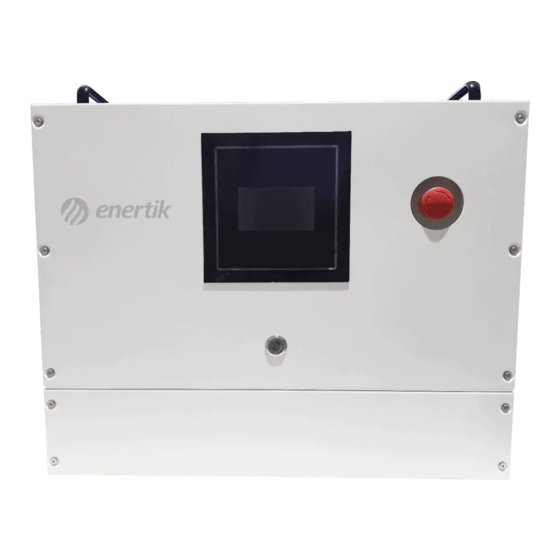
Page 9: Operation
3. OPERATION Power ON/OFF Once the unit has been properly installed and the batteries are connected well, simply press On/Off switch to turn on the unit. Operation and Display Panel The operation and display panel, shown in below chart, is on the front panel of the unit. It includes a LCD display, four touchable function keys and RGB LED Bar, indicating the operating status and input/output power information. -
Page 10: Lcd Display
LCD Display The LCD display information will be switched in turns by pressing “ ” “ ” button. The selectable information is switched as the following table in order. Display Items LCD Display AC input voltage in L1 phase->AC input voltage in L2 phase->AC input voltage in L3 phase (three phase voltage display in turns with 3s interval) - Page 11 AC input voltage in L1 phase AC Input Frequency Charger CV Voltage Charger Float Voltage Maximum Charger Current Battery Capacity Charging Current Bar Charging Voltage Charging Current Charging Watt CPU1 Firmware Version AC input voltage in L1 phase AC Input Frequency Charger CV Voltage Charger Float Voltage Maximum Charger Current Battery Capacity...
-
Page 12: Lcd Setting
LCD Setting ” After pressing and holding “ button for 3 seconds, the unit will enter setting mode. Press “ ” or “ ” button to select setting programs. And then, press “ ” button to confirm the selection or “ ”... - Page 13 100A(default) Max Charging Current The setting range is from 10A to 100A. Increment of each click is 10A. Auto(default) If selected, charger will do the charging stage control...
- Page 14 2-Stage If selected, charger will always charge battery with 2-stage (CC->Float). Charger stage selection 3-Stage If selected, charger will always charge battery with 3-stage (CC->CV->Float). Auto(Default) If selected, the time for the charger during CV stage is controlled by the charger automatically.
- Page 15 CV charging voltage in Program 07 may be different based on the battery type selection in program 02 and battery voltage setting in program 03. If 48V is selected in program 03, If AGM or Flooded is selected in program 02, the CV charging voltage is fixed in 56.4V.
- Page 16 Floating charging voltage in Program 08 may be different based on the battery type selection in program 02 and battery voltage setting in program 03. If 48V is selected in program 03, If AGM or Flooded is selected in program 02, the floating charging voltage is fixed in 54.0V.
- Page 17 Buzzer on(Default) Buzzer off Buzzer control Backlight on(Default) Backlight off Backlight control LED on(Default) LED off On/off control for RGB LED power solid on(Default) LED power cycling RGB LED effects...
-
Page 18: Fault Reference Code
Fault Reference Code Fault Code Fault Event Icon on Bus soft start time out Bus voltage over 460V Bus voltage under Bus voltage unbalance AC input current over AC input relay fail PFC driver circuit stop working Bus voltage over 470V Bus voltage over 480V AC input current unbalance PFC can’t communicate with LLC... - Page 19 LLC NTC temperature sensor fail DC output average voltage low 15V DC output voltage over 120V DC output short fault (rapid protection) DC bus voltage over Can’t charge battery Output diode or fuse fault LLC can’t communicate with PFC DC output current over Fan lock AC contactor loss fault DC contactor loss fault...
-
Page 20: Warning Indicator
Warning Indicator Warning Warning Event Audible Alarm Icon flashing Code AC input loss Beep once every second Communication between PFC and Beep once every second LLC loss AC input voltage high Beep once every second AC input voltage low Beep once every second Communication between LLC and Beep once every second PFC loss... -
Page 21: Trouble Shooting
4. TROUBLE SHOOTING Problem LCD/LED/Buzzer Explanation / Possible cause What to do 1. Communication between 1. Check if the connection No response internal module and LCD panel between internal module and No indication. after power on. board is failed. panel board is well. 2. - Page 22 1. Return to repair center. Fault code 11 AC input current unbalance 2. Check if key components like MOSFETs are well. Communication between PFC Fault code 13/65 Return to repair center. and LLC controller is failed 1. Return to repair center. Fault code 14 PFC NTC temperature sensor fail 2.
-
Page 23: Specifications
5. SPECIFICATIONS Model 100A 200A AC Input Nominal Input Voltage 380Vac± 5V (3Ph+N+PE) Nominal voltage Range 276~480VAC Nominal Input Frequency 45Hz~65Hz Input Voltage Waveform Sinusoidal (utility or generator) Low Loss Voltage 260Vac± 5V Low Loss Return Voltage 270Vac± 5V High Loss Voltage 475Vac±...
Need help?
Do you have a question about the 100A and is the answer not in the manual?
Questions and answers