Table of Contents
Advertisement
Quick Links
Advertisement
Table of Contents

Summary of Contents for FIRELINX CM-64
- Page 1 U S E R MA N U A L WWW. F I R E L I NX . COM (833) FIRELNX (347-3569)
-
Page 2: Table Of Contents
Contents CM-64 ...................................... 1 CM-64 Panel Diagram ................................. 1 Power Button .................................. 1 Fire Button ..................................1 Charge LEDs ..................................1 Control Buttons ................................1 Navigation Buttons................................2 Timing Controls ................................2 Numpad ................................... 2 Channel Selection ................................2 Mini USB Port .................................. 2 USB Input .................................. - Page 3 Buttons and Ports ................................13 Power Button ................................13 Repeater Button ................................13 Navigation Buttons................................ 13 Continuity Test ................................13 Firing Pins ..................................13 Power Input ................................... 14 Antenna Input ................................14 2-Wire ................................... 14 Firing Module Basic Setup ..............................14 Home Page ..................................
-
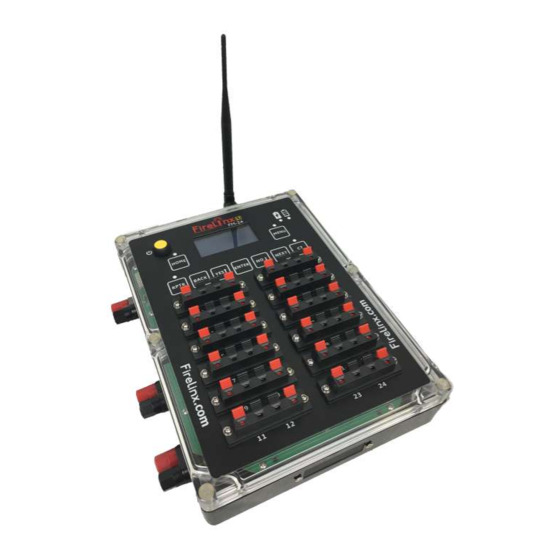
Page 4: Panel Diagram
CM-64 64 Channel Command Module CM-64 Panel Diagram Power Button This turns the Command Module (CM) on. Press and hold this button to power on the CM. Hold the button until the internal lights come on (about 3 seconds). If the... -
Page 5: Navigation Buttons
Plug the flash drive with the choreography or updates into this port. Files must be stored in the root directory of the drive. Cannot be used to connect to Figure 2 anything other than a USB memory stick or thumb drive. www.Firelinx.com... -
Page 6: 2-Wire Ports
The HOME, MENU, CT, WW, MOD, SHOW, and OPN buttons take you directly to the associated function page. Once on that page, other functions and displays may be reached. In Figure 4, the MENU screen is shown. Figure 4 www.Firelinx.com... -
Page 7: Basic Setup
If the top displays MANUAL with no folder icon, then no show file has been loaded. Only Manual firing will be allowed. To load a show file, insert a USB drive with the show file (.CSV format) in the root directory. Then go to MENU->FILE:(press #key 4 and Enter). www.Firelinx.com... - Page 8 ARM/SAFE button. The Firing Modules will blink Red/Yellow for a few seconds as the capacitor bank is being charged. Once charged, there is no recharge time requirement. All channels may be fired simultaneously. When charging is complete the system will automatically transition to the SHOW page. www.Firelinx.com...
- Page 9 Cues or Scripts. A choreography file can have any number of defined Cues, each may be one or more timed events in sequence. To change the Cue, simply enter the cue number on the Numpad on the SMPTE or INTRL main page. www.Firelinx.com...
-
Page 10: Home Page
6. Software Version - This is a scroll down indicator. Pressing the down arrow will display the current software version installed on the CM or FM. Menu To navigate to the desired function, press the icon number and Enter on the Numpad. Figure 9 www.Firelinx.com... -
Page 11: Caliber/Disables
Every FM must be “Joined” with a single CM in order to decrypt the messages. Once an FM is Joined, even another Firelinx CM in the same area cannot connect to that FM. When in the JOIN MODE menu, the menu will display the CM’s ID Figure 12 Number. -
Page 12: File
Firelinx generic show file formats. (To get a sample of what the Firelinx generic show file looks like go to www.firelinx.com) or refer to the Appendix. If there are more than 4 show files on the USB press the up and down arrow keys to scroll between the pages. Use the Numpad to select the file to download. -
Page 13: Reset
Often only a single component failure is the difference between testing an E-match and firing an E-match. CrewSafe™ is possible because Firelinx takes a “Nine Zeroes Safe” approach to continuity testing. That means the probability of accidentally firing a shell is very low. Use this feature only if the pyrotechnician in charge and the authority having jurisdiction concur that it is safe. -
Page 14: Wireless Wizard
(9) will be displayed lower right. OPD (Operator Presence Device) An Operator Presence Device (OPD) can be utilized in the Firelinx system. When an OPD is plugged into the CM, the OPD will automatically be activated. In order to fire a show, the OPD button must be pressed before the fire button is pressed and throughout the entire show. -
Page 15: Opn (Open Pyro Network)
32 additional firing pins to be added to the FM. The OPN-32 card has an industry standard Centronics-36 D-style connector that comes out the front side of the module and attaches to a standard 32 shot slat. www.Firelinx.com... -
Page 16: Buttons And Ports
CM, but this button allows the continuity results for this module to be viewed on the module screen. Firing Pins This is where e-matches/squibs can be inserted to fire. They are easily replaceable for cleaning, replacement or upgrade. www.Firelinx.com... -
Page 17: Power Input
CM and FM might not be on the same RF channel. The RF channel can be set manully by selecting the RF Channel option in the MENU. The Wireless Wizard function in the CM can only change the RF Channels of FMs already joined and communicating. www.Firelinx.com... -
Page 18: Home Page
Yellow, the FM is detecting that the continuity test system has failed an internal safety test and is not sending the test current through the firing pins. If this happens contact Firelinx support through www.firelinx.com. The screen will also display the following icons to show the status of each channel: •... -
Page 19: Menu
X means that there is not a shot loaded but is currently in the choreography on that pin. • * means that there is more resistance than expected on the pin, there might not be enough energy to reliably fire every shot on that line. www.Firelinx.com... -
Page 20: Troubleshooting And Maintenance
You may replace that block with another (contact Firelinx.com for replacements and spares) or if that block was recently changed or otherwise disconnected from the FM, it is likely that the two small connectors between the wiring block and the FM printed circuit board did not get seated properly. -
Page 21: Opening The Case
To change the battery, unplug the battery from the connector, and then install the new battery. Figure 28 Figure 29 5. Carefully reinstall the board back into the case, and do the above actions in reverse to put the FM back together. www.Firelinx.com... -
Page 22: Appendix
• Button – On the CM and FM, it is an item that triggers an action if pressed. • Caliber – The diameter of a shell of fireworks. Used in Firelinx to disable certain sized shells from the CM. •... - Page 23 • Pyro – A person that controls fireworks. • RCA – A type of connector that is used to transmit audio and video data. In Firelinx it is used to receive timecode data. • Short – In reference to a circuit, it means that two components have no resistance between them.
Need help?
Do you have a question about the CM-64 and is the answer not in the manual?
Questions and answers