Table of Contents
Advertisement
Quick Links
Advertisement
Table of Contents

Summary of Contents for AIE SQ Series
- Page 1 SQ10000 INSTALL & MAINTENANCE MANUAL...
-
Page 2: Table Of Contents
TABLE OF CONTENTS SAFETY INTRODUCTION MODEL IDENTIFICATION SPECIFICATIONS PACKAGE CONTENTS LOCATION OF IMPORTANT COMPONENTS AND CONNECTIONS FUEL RECOMMENDATIONS ENGINE OIL RECOMMENDATIONS STARTING BATTERIES OPERATOR INTERFACE INSTALLATION MOUNTING THE GENSET FUEL TANK INSTALLATION HIGH VOLTAGE ELECTRICAL CONNECTIONS AC WIRING TERMINATION AUXILIARY WARNING, SHUTDOWN, AND EMERGENCY STOP WIRING AUTO MODE REMOTE START SETUP CONNECTING THE BATTERY OPERATION... -
Page 3: Safety
OPERATING IN COLD AMBIENT TEMPERATURES OPERATING IN DIRTY ENVIRONMENTS BREAKING IN A NEW ENGINE STORAGE AND RETURNING TO SERVICE MAINTENANCE TROUBLESHOOTING/ FAULT ICONS APPENDIX A: DC WIRING SCHEMATIC APPENDIX B: AC WIRING SCHEMATIC SAFETY Thoroughly read this manual before operating the genset. The following symbols are used throughout this manual and on the genset to warn of the potential hazards to the operator, service personnel, or equipment. - Page 4 EXHAUST GAS IS DEADLY • Engine exhaust fumes can be very harmful if allowed to accumulate. Only operate the engine in a well-ventilated area. Inspect for exhaust leaks at every startup and after every eight hours of operation. • • Exposure to exhaust gases can cause carbon monoxide poisoning.
- Page 5 MOVING PARTS CAN CAUSE SEVERE PERSONAL INJURY OR DEATH • Disable any automatic starting systems before performing inspections or service on the genset to avoid unexpected start. • Do not wear loose clothing or jewelry near moving parts such as fans, belts and pulleys. •...
-
Page 6: Introduction
INTRODUCTION This manual covers the installation, first run operation, and maintenance of the SQ Genset. Be sure to read the entire manual thoroughly before first use and obey all safety warning information contained within. Proper installation and use as described in this manual will ensure your genset operates at peak performance. - Page 7 The engine model and serial number can be found either on genset baseframe just inside the genset door, to the right. OR on top of the control panel box. Engine Model and Serial Number Locations NOTE: You should record the model and serial numbers below for quick reference in the future. MODEL # SERIAL # GENSET:...
-
Page 8: Specifications
SPECIFICATIONS MODEL UNIT SQ9000 SQ10000 GENERATOR Manufacturer Linz Model CPT18MF 4-pole, rotating field Type Exciter Type Brushless, self-exciting Frequency 12, Reconfigurable No. Leads Rated Voltage 120/240 120/208 120/208/240 277/480 120/240 120/208 120/208/240 277/480 Phase ø Single Three Three Delta Three Single Three Three Delta... -
Page 9: Package Contents
MODEL UNIT SQ9000 SQ10000 GENERATOR SET Standby Power kW (kVA) 8.6 (8.6) 8.6 (10.7) 10.0 (10.0) 10.0 (12.5) Prime Power kW (kVA) 7.7 (7.7) 7.7 (9.5) 8.9 (8.9) 8.9 (11.0) Governor Type Mechanical Fuel Consumption (100% 0.77 0.89 Load) Fuel Consumption (75% 0.58 0.67 Load) -
Page 10: Location Of Important Components And Connections
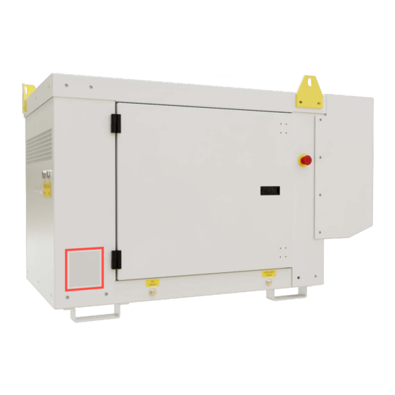
LOCATION OF IMPORTANT COMPONENTS AND CONNECTIONS The location of components needed for operation and maintenance are shown below. For more details see the MAINTENANCE section on page 26. NUMBER ITEM / FUNCTION Air Inlet Radiator Air Outlet Generator Wiring Access Cover Radiator Cap Access Cover Main Access Door... - Page 11 NUMBER ITEM / FUNCTION Exhaust Outlet Fuel Supply Port Fuel Return Port Breaker/Generator Box Fuel Filter Drive Belt Figure 3: Important Components (cont.) / 33 ai-engines.com info@ai-engines.com rev 1.2 (08/15/22)
-
Page 12: Fuel Recommendations
FUEL RECOMMENDATIONS ***Diesel fuel is combustible and can cause severe personal injury or death. Do not smoke near diesel fuel tanks or equipment. Keep all flames, sparks, or all other sources of ignition well away.*** The use of ultra-low sulfur fuel (15ppm or 0.0015 wt.%) is mandatory when operated in US EPA regulated areas. The use of Kerosene, whether blended with diesel or otherwise is prohibited within US EPA regulated areas. -
Page 13: Starting Batteries
STARTING BATTERIES The genset uses a 12V direct current starting, charging and control system. The battery is a 500 CCA, sealed type. Regular maintenance of the battery may be required in order to ensure proper starting performance. The genset is shipped with the battery disconnected and will need to be connected before first running the genset. -
Page 14: Installation
Auto Mode Button - This button will toggle the control panel in and out of Auto mode. This is only applicable if a remote start STARTING THE GENSET signal has been connected to the control panel. See on page 20 for operating instructions. Manual/Start Mode Button - This button will initiate the pre-heat and start sequence when the engine is in stop mode. -
Page 15: Mounting The Genset
Many engine components and fluids can be hot and cause severe burning on contact. Exhaust piping, engine oil, engine coolant, exhaust insulation, radiator core, and other parts can become extremely hot after extended operation. Do not work on a genset until it has sufficiently cooled. -
Page 16: Fuel Tank Installation
FUEL TANK INSTALLATION The SQ Genset is intended to draw from a nearby tank or a sub-base fuel tank below the unit. The genset is shipped with labeled fuel supply (5/16”) and return (3/16”) barb connections. Fuel lines should be routed so that the fuel lines are not kinked, pinched, or unprotected around sharp edges as they are routed to the fuel tank, secured as needed. -
Page 17: High Voltage Electrical Connections
HIGH VOLTAGE ELECTRICAL CONNECTIONS All wiring must comply with local electrical codes. A qualified electrician must perform all electrical wiring connections. All SQ Genset generators are supplied with a main circuit breaker, control panel voltage sense lead fuses, and a distribution block inside the generator box, see Figure 3 on page 10 and 11 to locate the breaker. -
Page 18: Auxiliary Warning, Shutdown, And Emergency Stop Wiring
AUXILIARY WARNING, SHUTDOWN, AND EMERGENCY STOP WIRING By default, the SQ90000/SQ10000 uses a red mushroom-style emergency stop to activate the Emergency Stop shutdown for the engine. When the emergency stop input is active (grounded), the engine will not be allowed to crank or run under any circumstances. -
Page 19: Auto Mode Remote Start Setup
AUTO MODE REMOTE START SETUP (ADD WIRING DIAGRAMS) The standard 3110 DSE Control Panel comes preset to accept a remote start input. To do this Pin #1 and #6 of the 8 pin Deutsch plug need to be connected together while the control panel is turned on and in Auto Mode. When the wires are connected together the unit will begin its start sequence, start, and run automatically. -
Page 20: Pre-Start Checks
PRE-START CHECKS In order to prevent problems and identify maintenance situations early, it is important to perform a pre-start check before each use of the genset. Before each start: Check for oil and coolant leakage Check all air inlets and outlet for obstructions or clogging Check radiator fins for clogging Check for signs of fuel leaks, exhaust leaks or damage to either system Check belt tension... - Page 21 ICON DISPLAYED CONTROL PANEL MODE Stop Mode: The genset is stopped with no oil pressure and ready for a manual start. Auto Mode: The genset is stopped and in Auto Mode, waiting for an remote start input to tun on genset Running Mode: The genset is running with no faults.
- Page 22 After the genset starts, a 10 second Safety On timer activates and the timer icon is displayed. The safety timer allows Oil Pressure, High Coolant Temperature, Under-speed, Charge Fail and any delayed Auxiliary fault inputs to stabilize without triggering a fault. Once the engine is running and the Safety On timer has expired, the animated run icon is displayed.
-
Page 23: Stopping The Genset
STOPPING THE GENSET MANUALLY When operating in manual mode, under normal circumstances, to stop the genset: Turn off or disconnect all electrical loads. Allow the genset to cool down for about 5 minutes. Press the red STOP button on the control panel. Turn the On/Off switch to the OFF position. - Page 24 OPERATING IN COLD AMBIENT TEMPERATURES When operating in low temperature ambient conditions, be sure to use the correct engine oil viscosity, see Figure 4 page 12. When starting in cold weather, it may be necessary to allow the engine to complete more than one preheat and crank cycle to start.
- Page 25 STORAGE AND RETURNING TO SERVICE • Secure the genset to prevent movement during operation. • To not stand near or under the genset while it is suspended. • The genset is heavy; use only equipment capable of handling such loads. •...
- Page 26 MAINTENANCE Periodic maintenance is the single most important factor for genset life and performance. Figure 12 outlines the recommended maintenance items for normal genset use. If you are operating in exceptionally hot or dusty environments, more frequent service may be required. Please refer to the supplied Kubota Operators Manual for specific maintenance procedures. FIRST EVERY EVERY...
- Page 27 TROUBLESHOOTING/ FAULT ICONS Always perform checks in the STOP condition, except checks that require the generator to be running. Keep hands and loose clothing away from rotating parts at all times during operation. Hot engine parts can cause severe burns. Allow the engine to cool before performing any checks. If you are experiencing trouble with your genset, use the tables below to try and resolve your issue.
- Page 28 TROUBLE CAUSE SOLUTION Insufficient engine oil pressure Check engine oil level and add oil as needed. Lubrication system malfunctioning See an authorized Kubota engine dealer Panel shows LOW OIL PRESSURE fault icon: Oil pressure switch faulty Replace oil pressure switch Also see “Engine stops unexpectedly”...
- Page 29 TROUBLE CAUSE SOLUTION Panel shows OVERSPEED fault icon Governor rebound from sudden Stage the shutoff of different electrical loads when engine stops loss of load Governor unable to regulate See authorized Kubota engine dealer engine speed Output frequency exceeds 70Hz. ENIGNE STOPS UNEXPECTEDLY Panel shows UNDERVOLTAGE fault Loss of engine speed...
- Page 30 TROUBLE CAUSE SOLUTION Refill fuel tank. Fuel shortage Check all fuel connections for loose or damaged fasteners. Replace if necessary Engine cranks but does not start. Air or water in fuel system Bleed air from fuel lines Control panel displaying FAIL TO Remove water from fuel tank START fault symbol after 3 crank Check fuel filter.
- Page 31 APPENDIX A: DC WIRING SCHEMATIC / 33 ai-engines.com info@ai-engines.com rev 1.2 (08/15/22)
- Page 32 APPENDIX B: AC WIRING SCHEMATIC / 33 ai-engines.com info@ai-engines.com rev 1.2 (08/15/22)
- Page 33 / 33 ai-engines.com info@ai-engines.com rev 1.2 (08/15/22)
Need help?
Do you have a question about the SQ Series and is the answer not in the manual?
Questions and answers