Table of Contents
Advertisement
Quick Links
Advertisement
Table of Contents

Summary of Contents for Parker Products PTS-250
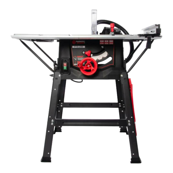
- Page 1 CLICK TO CHANGE TEXT TABLE SAW PTS-250 OWNERS MANUAL...
-
Page 2: Table Of Contents
INTRODUCTION CONTENTS This manual has been produced by Parker Products Ltd. and should be kept with the product and referenced GENERAL SAFETY RULES ....................4-5 for operation, maintenance and troubleshooting. SAFETY SYMBOLS ........................6-7 This manual contains an overall description of the product, together with all the necessary information for using the FOR SAFE OPERATION ...................... -
Page 3: General Safety Rules
GENERAL SAFETY GENERAL SAFETY For safe operation and maintenance symbols are moulded in relief on the machine or shown on a label. • READ THIS MANUAL CAREFULLY BEFORE USING THIS MACHINE. WARNING CLOTHING • WARNING! Never allow children or anyone who does not fully understand the directions given in the manual to use the machine. To reduce the risk of injury, user must read Appropriate clothing should be worn during •... -
Page 4: Safety Symbols
SAFETY SYMBOLS SAFETY SYMBOLS This symbol, before a safety comment, indicates a - Volts PRECAUTION, a WARNING or a DANGER. Ignoring WARNING! To reduce the risk of injury, this warning can lead to an accident for yourself or for Double Insulated user must read instruction manual. -
Page 5: For Safe Operation
FOR SAFE OPERATION FOR SAFE OPERATION IMPORTANT VIBRATION HANDLING LABELS & SYMBOLS • For your own safety, please read these operating and safety • WARNING: When using this machine the operator can be exposed • • Handle the machine with care, allowing the machine to do the work. WARNING: Do not operate this machine if warning and/or •... - Page 6 FOR SAFE OPERATION FOR SAFE OPERATION • • • WARNING: This machine is not intended for use by persons OUTDOOR USE WARNING: Read all safety warnings and instructions. pipes, radiators, ranges and refrigerators. There is an increased risk of (including children) with reduced physical,sensory or mental Failure to follow the warnings and instructions may result in electric shock if your body is earthed or grounded •...
- Page 7 FOR SAFE OPERATION FOR SAFE OPERATION • c) Prevent unintentional starting. Ensure the switch is in the dangerous and must be repaired This will ensure that the safety of the power tool is maintained. Work with approved safety equiptment, such as dust masks that are off-position before connecting to power source and or battery pack, c) Disconnect the power tool from the power source and/or battery specially designed to filter microscopic particles...
- Page 8 FOR SAFE OPERATION FOR SAFE OPERATION • Take care that the selection of the saw blade is suitable for the regularly and replace it if it is worn. Use only the riving knife as this is operation is dusty. Everyday eyeglases only have impact resistant use the guards for handling or transportation.
-
Page 9: What's In The Box
WHAT’S IN THE BOX WHAT’S IN THE BOX OPERATION MAIN BODY LEGS RUBBER FEET RIP FENCE MITRE GAUGE + 8 HEX HEAD SCREWS PRE INSALLED IN MAIN BODY CANTILEVER BRACES FENCE RAIL EXTRACTION HOSE + JOINING TONGUE BLADE GUARD PUSH STICK LEG BRACES TABLE EXTENSION 2x LONG... -
Page 10: Product Features
PRODUCT FEATURES PRODUCT FEATURES SLIDING MITRE RIVING TILT EXTRACTION GAUGE KNIFE KNOB HOSE ON/OFF BLADE EXTRACTION SPANNERS SWITCH FENCE POINT HAND PROTRACTOR BLADE PUSH SCALE & BLADE GUARD WHEEL STICK... -
Page 11: Assembly
ASSEMBLY ASSEMBLY TURN MAIN BODY UPSIDE DOWN REMOVE BOLTS FROM BODY ATTACH LEGS REPEAT PROCESS ATTACH RUBBER FEET Position the table upside down on a protected sur- Loosen and remove the bolts. Attach the four legs (stamped A) to the main body. Repeat the process of fitting the legs tightening all Fit the rubber feet into position by pushing into face such as a workbench or tabletop. - Page 12 ASSEMBLY ASSEMBLY ATTACH FRONT, REAR & SIDE LEG BRACES ATTACH TABLE EXTENSION BOLT ON TABLE EXTENSION EXTENSION SUPPORT BAR The front and rear side braces are longer and are stamped with letter B. Fit both into place. The side braces are Align the screw holes on the table Identify the highlighted pre-drilled holes.
- Page 13 ASSEMBLY ASSEMBLY EXTENSION SUPPORT STRUT ATTACH STRUT TO BODY REPEAT PROCESS STAND MACHINE ON LEGS ATTACH REAR CANTILEVERS PUSH STICK HANGER Fix the extension support struts, tightening Attach the support struts onto the table side. Repeat Process. Note that the Hole is oval Turn table over to upright position.
- Page 14 ASSEMBLY ASSEMBLY SLIDE ON THE FENCE RAIL CONNECT FENCE RAIL ADJUST THE FENCE RAIL ATTACH THE COACH BOLTS Attach all 7 coach bolts utilising the suplied flange Slide the fence rail over the protruding bolts and Connect the fence rail. Ensure the rail is positioned To adjust the fence rail correctly, place the rip fence nuts.
- Page 15 ASSEMBLY ASSEMBLY LOCATE & REMOVE ACCESS PANEL LOOSEN RETAINING BOLT & PLATE ATTACH RIVING KNIFE ADJUST RIVING KNIFE RAISE THE BLADE 3-5mm Raise the blade to maximum height as indicated. Identify the access panel as shown. Unscrew the Look inside and identify the retaining plate with bolt Once the bolt and plate are loose enough, slide the You can adjust the riving knife as required by access panel screw in the normal way.
- Page 16 ASSEMBLY ASSEMBLY TOP BLADE GUARD FIT GUARD TO RIVING KNIFE ADJUST BLADE GUARD ATTACH EXTRACTION HOSE TO GUARD ATTACH EXTRACTION HOSE TO BODY The top blade guard must always be fitted Raise the cutting blade to the full height. To adjust loosen the wing nut and move the The extraction hose is a simple push fit.
-
Page 17: Checking/Adjusting The Rip Fence
CHECKING/ADJUSTING THE RIP FENCE CHECKING/ADJUSTING THE RIP FENCE RIP FENCE CHECK THE RIP FENCE IS PARALLEL ADJUST ALIGN TO BLADE THE DUAL READ SCALE LOCKING LEVER The rip fence simply slots into the fence rail Be sure that when fitting the rip fence is The rip-fence face plate can be repositioned It is recommended that the rip fence is The rip fence guide provides a window to... -
Page 18: Sliding Mitre Guage
SLIDING MITRE GAUGE SLIDING MITRE GAUGE THE MITRE GAUGE FIT THE MITRE GAUGE ADJUST THE MITRE GAUGE TIGHTEN THE MITRE GAUGE The sliding mitre gauge can be repositioned as re- The adjustable face plate is held in the protractor The mitre gauge slots into either of the inverted To set the angle that you desire simply loosen the quired and is fully adjustable. -
Page 19: Push Stick
PUSH STICK OPERATION USING THE PUSH STICK STORING THE PUSH STICK ON/OFF SAFETY SWITCH & OVERLOAD PROTECTION The push stick is for safe cutting - essential for cuts The push stick is stored on the right-hand front leg. The green ON switch (I) starts the machine. The red OFF switch (O) stops the machine. -
Page 20: Operation
OPERATION OPERATION RAISING THE BLADE LOWERING THE BLADE TILTING THE BLADE ADJUSTING THE BLADE ANGLE USING THE PROTRACTOR SCALE SECURING BLADE ANGLE To raise the blade simply turn the wheel To lower the blade simply turn the wheel in To tilt the angle of the blade (up to 45 Push the turning wheel into the inner Adjust to the angle required. -
Page 21: Maintenance
MAINTENANCE MAINTENANCE CHANGING THE BLADE REMOVE ACCESS PANEL OUTER FLANGE & ARBOR NUT BLADE CHANGING SPANNERS FIT BLADE RE-ASSEMBLE Completely disconnect the saw from the Remove access panel by loosening the Raise blade to highest position. You will need Use the hexagonal spanner to remove the The inner flange can stay in position. - Page 22 MAINTENANCE REMOVE ALL SAW DUST AIR LINE/VACUUM WIPE WITH DAMP CLOTH THIS PAGE HAS INTENTIONALLY BEEN LEFT BLANK Use a soft brush to clear away any debris Use a workshop Air line or a vacuum to Only use a damp cloth to wipe down the left behind from using the machine.
-
Page 23: Troubleshooting
TROUBLESHOOTING TROUBLESHOOTING PROBLEM POSSIBLE CAUSE SOLUTION PROBLEM POSSIBLE CAUSE SOLUTION Rip fence out of alignment Align rip fence with blade Saw not plugged in Plug in the machine Riving knife not aligned with blade Align riving knife with blade Saw will not start Fuse blown or circuit breaker tripped Replace fuse or reset circuit breaker (32 amp recomended consult an electrician) Feeding stock without rip fence... -
Page 24: Specifications
SPECIFICATION GUARANTEE MACHINE Motor (UK/EU 220-240v ~ 50/60Hz- 2000W (S6 25%) Table Dimensions - 583 x 893mm Riving Knife Thickness - 1.8mm Parker Products Ltd Guarantees the product against defective material or damage for period of 12 Speed No Load - 5000min-1 months from the date of purchase. -
Page 25: Declaration Of Conformity
☑ EN 55014-2:1997/A2:2008 Protection class: II ☑ EN 55014-2:2015 ☑ EN 61000-3-2:2014 Model/Type: ☑ EN 61000-3-11:2000 PTS-250 ☑ EN 62841-1:2015 • ☑ EN 62841-3-1: 2014/A11: 2017 Manufacturing Date/Serial Number: 2020 Having been type examined to the requirements of the directives by: TÜV SÜD Product Service GmbH,... - Page 26 PTS-250 WWW.PARKERBRAND.CO.UK February 2020 Rev 1.1...
Need help?
Do you have a question about the PTS-250 and is the answer not in the manual?
Questions and answers