Table of Contents
Advertisement
Quick Links
OWNER'S MANUAL
Thank-you and congratulations for purchasing a high quality Airmac air compressor set.
It has been designed and manufactured to provide many years of safe and reliable
service if installed, operated and maintained in accordance with these instructions.
Please read and understand this manual before operating the compressor. Failure to
do so could result in death, severe injury and/or substantial property damage.
This manual should be considered a permanent part of the compressor and should
remain with it if resold.
72 Platinum Street, Crestmead, QLD 4132, Australia
Phone: (07) 3803 4100
Fax: (07) 3803 1255
Email: sales@glencomfg.com.au
Web:
www.glencomfg.com.au
Advertisement
Table of Contents
Troubleshooting

Summary of Contents for GLENCO AIRMAC FU SHENG T20
- Page 1 OWNER’S MANUAL Thank-you and congratulations for purchasing a high quality Airmac air compressor set. It has been designed and manufactured to provide many years of safe and reliable service if installed, operated and maintained in accordance with these instructions. Please read and understand this manual before operating the compressor. Failure to do so could result in death, severe injury and/or substantial property damage.
- Page 2 Release air slowly when draining condensate water or depressurizing the compressor. Do not connect the compressor to air handling parts that cannot withstand the compressor’s maximum design pressure (refer to tank nameplate). August 2006 © Glenco Manufacturing Pty Ltd Page 2 of 44...
- Page 3 Do not permit anyone to operate the compressor without proper instruction. August 2006 © Glenco Manufacturing Pty Ltd Page 3 of 44...
- Page 4 The information is correct at the date of publication. Due to Glenco Manufacturing Pty Ltd’s policy of continued product development, some features and specifications of your new air compressor may vary slightly from those shown herein.
-
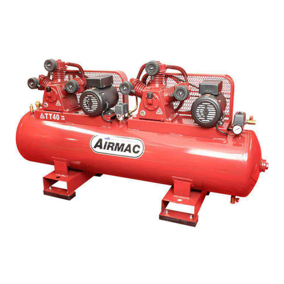
Page 5: Product Familiarization
Unloading Line Oil Level Sight Glass Safety Valve Compressor Pump Nameplate Drain Valve Electric Motor Discharge Outlet Air Receiver Tank Pressure Gauge Air Receiver Tank Nameplate Pressure Switch Drive Guard August 2006 © Glenco Manufacturing Pty Ltd Page 5 of 44... - Page 6 Oil Drain Plug Drain Valve Oil Level Sight Glass Discharge Outlet Valve Compressor Pump Nameplate Pressure Gauge Electric Motor Pressure Switch Air Receiver Tank Dual DOL Starter Drive Guard August 2006 © Glenco Manufacturing Pty Ltd Page 6 of 44...
- Page 7 Oil Fill Cap Safety Valve Oil Drain Plug Drain Valve Oil Level Sight Glass Discharge Outlet Valve Electric Motor Pressure Gauge Air Receiver Tank Pressure Switch Air Receiver Tank Nameplate August 2006 © Glenco Manufacturing Pty Ltd Page 7 of 44...
- Page 8 Drain Valve Oil Drain Plug Discharge Outlet Valve Oil Level Sight Glass Pressure Gauge Electric Motor Pressure Switch Air Receiver Tank Star-Delta Starter Drive Guard Solenoid Valve Foot Mount August 2006 © Glenco Manufacturing Pty Ltd Page 8 of 44...
- Page 9 Unloading Line Oil Level Sight Glass Safety Valve Petrol Engine Drain Valve Air Receiver Tank Discharge Outlet Air Receiver Tank Nameplate Pressure Gauge Drive Guard Pilot Valve Wheel Mounting Bracket August 2006 © Glenco Manufacturing Pty Ltd Page 9 of 44...
- Page 10 Oil Drain Plug Unloading Line Oil Level Sight Glass Safety Valve Compressor Pump Nameplate Drain Valve Diesel Engine Discharge Outlet Valve Air Receiver Tank Pressure Gauge Drive Guard Pilot Valve August 2006 © Glenco Manufacturing Pty Ltd Page 10 of 44...
-
Page 11: Application And Function
The requisite power to drive the compressor pump is provided by the prime mover, i.e. electric motor, petrol engine or diesel engine, through a V-belt transmission. August 2006 © Glenco Manufacturing Pty Ltd Page 11 of 44... - Page 12 Australian Standard AS 1210 and all Australian Occupational or Workplace Health and Safety Regulations. A copy of the Manufacturer’s Data Report (as per AS 4458) is available from Glenco Manufacturing Pty Ltd upon request. August 2006 © Glenco Manufacturing Pty Ltd...
- Page 13 A drain valve is fitted to the bottom of the air receiver tank to permit the release of water condensate that would otherwise corrode the tank and damage pneumatic devices. The pressure within the air receiver tank is indicated on the pressure gauge. August 2006 © Glenco Manufacturing Pty Ltd Page 13 of 44...
-
Page 14: Receipt And Inspection
Make sure that electrical enclosures and components are appropriate for the installation environment. August 2006 © Glenco Manufacturing Pty Ltd Page 14 of 44... -
Page 15: Installation
Do not bolt uneven feet tightly to the foundation as this will cause excessive stress on the air receiver tank. Use metal August 2006 © Glenco Manufacturing Pty Ltd Page 15 of 44... - Page 16 Ambient Temperature The air compressor is designed for operation in ambient temperatures of between 0° C (32° F) and 40° C (104° F). Noise Considerations August 2006 © Glenco Manufacturing Pty Ltd Page 16 of 44...
- Page 17 1-1/2” 1-1/2” Air hose should be sized in accordance with Table 2, and again with consideration as to whether the hose is a distribution line or a branch line. August 2006 © Glenco Manufacturing Pty Ltd Page 17 of 44...
- Page 18 240 Volt Air Compressors These models are shipped pre-wired with a compliant flexible lead and three-pin plug ready for “plug and play” installation. August 2006 © Glenco Manufacturing Pty Ltd Page 18 of 44...
- Page 19 Each 415 Volt compressor is fitted with an adjustable automatic reset thermal overload relay that is either built into the pressure switch or the star-delta starter. August 2006 © Glenco Manufacturing Pty Ltd Page 19 of 44...
- Page 20 Remove any corrosion, and coat the terminals and cable ends with corrosion-preventing grease. Remove the cable from the battery negative (−) terminal before carrying out any maintenance or repairs. August 2006 © Glenco Manufacturing Pty Ltd Page 20 of 44...
-
Page 21: Operation
650 kPa (94 psi). It will also stop automatically whenever the air receiver pressure reaches approximately 870 kPa (126 psi). August 2006 © Glenco Manufacturing Pty Ltd Page 21 of 44... - Page 22 “OFF” position and that the emergency stop button is released (which can be verified by turning the stop button head clockwise one-quarter of a turn). Check that the compressor’s pressure switch is turned to the “OFF” position. August 2006 © Glenco Manufacturing Pty Ltd Page 22 of 44...
- Page 23 • If the engine doesn’t start, repeat the previous step. To start using the engine’s electric starter, if fitted: August 2006 © Glenco Manufacturing Pty Ltd Page 23 of 44...
- Page 24 To start using the engine’s recoil (or “rope”) starter: • Pull the starter handle slowly until strong resistance is felt and then return it slowly. • Push the engine decompression lever down and release it. August 2006 © Glenco Manufacturing Pty Ltd Page 24 of 44...
- Page 25 “OFF” position (after turning off the engine using the fuel stop lever). • Close the engine fuel supply valve. Duty Cycle To maximize service life, the air compressor should be adequately sized for its given application. August 2006 © Glenco Manufacturing Pty Ltd Page 25 of 44...
- Page 26 The parallel operation of individual compressors supplying a common air system can often result in very unbalanced duty cycles amongst the units unless they share a single controller. August 2006 © Glenco Manufacturing Pty Ltd Page 26 of 44...
-
Page 27: Maintenance And Repair
500 Hrs 2,000 Hrs Activity 1 Day 1 Week 1 Month Clean Unit ● Check V-Belt(s) ● Tighten Joints & Fasteners ● Replace Oil ● Replace Air Filter(s) ● August 2006 © Glenco Manufacturing Pty Ltd Page 27 of 44... - Page 28 Use extreme caution when opening the drain valve if the air receiver tank is pressurized. Thumbscrew drain cocks should not be opened more than one full turn. Lever operated drain valves can be fully opened with one quarter of a turn. August 2006 © Glenco Manufacturing Pty Ltd Page 28 of 44...
- Page 29 Oil and grease marks should be cleaned off using mild household surface cleaner and a soft rag. Do not use abrasive cleaners or strong solvents that can damage the compressor’s paint finish. V-Belt(s) August 2006 © Glenco Manufacturing Pty Ltd Page 29 of 44...
- Page 30 Standard M5 Bolt or Nut Standard M6 Bolt or Nut Standard M8 Bolt or Nut 17.5 Standard M10 Bolt or Nut 37.5 27.5 Standard M12 Bolt or Nut 40.5 August 2006 © Glenco Manufacturing Pty Ltd Page 30 of 44...
- Page 31 12 Volt Battery If installed, the factory fitted 12 Volt battery is a maintenance free type. Ensure correct polarity whenever charging or refitting the battery as described in the Installation section. August 2006 © Glenco Manufacturing Pty Ltd Page 31 of 44...
-
Page 32: Troubleshooting
It is recommended for your convenience and expedience that the troubleshooting guide is consulted prior to contacting an Airmac dealer or Glenco Manufacturing Pty Ltd for advice. Refer to the separate Owner’s Manual for instructions about the petrol or diesel engine, if fitted. -
Page 33: Troubleshooting Chart
(nil or complete pressure switch. restricted unloading air flow). 12. Nil or restricted discharge 12. Repair or replace non- air flow through non- return valve. return valve. August 2006 © Glenco Manufacturing Pty Ltd Page 33 of 44... - Page 34 4. Engine throttle control not 4. Adjust or replace throttle opening fully or engine cable. See engine fault. manual for other action. 5. Damaged or worn 5. Replace compressor August 2006 © Glenco Manufacturing Pty Ltd Page 34 of 44...
- Page 35 V- loose/worn V-belts. belt tension. 5. Head unloaders not fully 5. Repair or replace head retracting (usually unloaders. indicated by air blowing out from air filter inlets). August 2006 © Glenco Manufacturing Pty Ltd Page 35 of 44...
- Page 36 2. Drain oil down to high level mark. 3. Low oil viscosity. 3. Replace with correct oil. 4. Excessive duty cycle. 4. Reduce air demand or use larger or additional compressor(s). August 2006 © Glenco Manufacturing Pty Ltd Page 36 of 44...
- Page 37 1. Replace unloader valve or from pressure switch during unloader valve. complete pressure switch. pumping mode. Air receiver tank does not 1. Faulty non-return valve. 1. Repair or replace non- August 2006 © Glenco Manufacturing Pty Ltd Page 37 of 44...
- Page 38 1. Replace oil. glass. cast iron material (initial oil fill only). 2. Oil dirty and/or 2. Replace oil and check for overheated (initial or compressor pump subsequent oil fill). overheating. August 2006 © Glenco Manufacturing Pty Ltd Page 38 of 44...
- Page 39 If so, ensure that the party receiving the compressor is notified accordingly. Keep the compressor covered during transport to prevent the ingress of dust and debris. August 2006 © Glenco Manufacturing Pty Ltd Page 39 of 44...
- Page 40 At this point, the engine’s inlet and exhaust valves should be closed during the compression stroke and this should help to prevent rust forming inside the cylinder while the engine is not is use. August 2006 © Glenco Manufacturing Pty Ltd Page 40 of 44...
-
Page 41: Dismantling And Disposal
Take the unwanted unit or components to your local recycling centre instead. The compressor is almost entirely made of metal that can usually be sold to scrap metal recyclers. August 2006 © Glenco Manufacturing Pty Ltd Page 41 of 44... -
Page 42: Warranty
It is recommended that you keep a copy of the tax invoice with this manual. Warranty Conditions Glenco Manufacturing Pty Ltd (the “Company”) warrants that the Goods manufactured by it shall be free from defects in material and workmanship for a period of twelve (12) months from the date of original sale (hereinafter the “Warranty Period”). - Page 43 The choice of remedy will be at the discretion of the Company and the Purchaser acknowledges that this limitation of liability is fair and reasonable. August 2006 © Glenco Manufacturing Pty Ltd Page 43 of 44...
-
Page 44: Maintenance And Repair Record
Airmac Owner’s Manual MAINTENANCE AND REPAIR RECORD Date Maintenance or Repair Activity August 2006 © Glenco Manufacturing Pty Ltd Page 44 of 44...
Need help?
Do you have a question about the AIRMAC FU SHENG T20 and is the answer not in the manual?
Questions and answers