Advertisement
Quick Links
Advertisement

Related Manuals for BelFox 47-21-i


Summary of Contents for BelFox 47-21-i
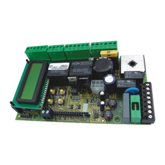
- Page 1 Control board 47-21-i for Ultra VA, Genios 125 – 210, Genios 350 and Drive Portal Instruction manual Comfort and safety with Gewerbestraße 3-5 D - 36148 Kalbach a press Tel.: 0 900/1101913 Fax: 0 66 55 / 96 95-31 of a button E-Mail: info@belfox.de...
- Page 3 1.) Control elements of the board 1 a) Display The control board 47-21-i is equipped with a standard illuminated display for easy programming and trouble shooting. 1 b) Buttons 4 buttons are installed on the control for easy menu access and control.
-
Page 4: Wire Connections
2.) Wire connections 2 a) Plan for wire connections Removeble terminal blocks (SL1 – SL8) for easy external wire connection have been placed on the board. This system enables easy replacement of the controller board if necessary. DANGER ! Prior to connecting, all terminal blocks must be voltage free! Danger! Terminals 1 to 8 are connected to 230 volts! Do not apply any main voltage to the terminals 9 to 36! The improper use/operation could damage the control board and the guarantee claim... - Page 5 2 c) Terminal blocks [Detailed connections] Connector block 1 (SL1) – High voltage terminal Terminal 1 & 2: Connection of the 230V/ 50Hz power supply (1-L / 2-N) connected in the factory. Terminal 3 & 4: Connection of the 230V / 50Hz primary side of the transformer (3-N / 4-L) connected in the factory.
- Page 6 Connector block 7 (SL7) – Safety input Stop & light barrier (for potential-free opening contacts, see 2e & 2f) Terminal 27 & 28: Stop input – Wicket door safety input Terminal 29 & 30: Connection of the safety light barrier (for the opening contact of the light barrier) Connector block 8 (SL8) –...
- Page 7 2 e) Light barrier Power supply: The supply voltage can be tapped from the control board. Terminal 1+2 =230 AC (mains voltage) Terminal 11+12 =24V AC (Alternative current – in use of power supply with transformer) Terminal 13+14 =24V DC (Direct current) The potential-free opening contact (closed when inactive) of a light barrier can be connected to the terminals 29 &...
- Page 8 2 h) Optoelectronical safety contact edges (OES) It is possible to connect optoelectrical safety contact edges between the terminals 31 and 34. The power supply of the OES DC 12V has to be connected to the terminal 34=mass and to 31=+12V max. 150mA. The OSE1 has to be connected to the terminal 32 and the OSE2 to the terminal 33.
- Page 9 3.) Programming 3 a) General programming Use the 4 buttons positioned on the control board in order to programm the controller. (see 1b). Use the buttons „ top left“ and „ down left“ with the symbols „ ↑+“ and „ ↓-“ in order to select and confirm your choices in the menu items.
- Page 10 3 b) Configuration of software functions Caution: Every time the parameters are changed the memorized runs must be learnt again! Press „ Escape/Menu“ until, „ Menu“ appears in the display. Enter with the button „ / Return“ . Use the buttons „ ↑+“ and „ ↓-“ -“ in order to select the desired functions/options, which will be described in the following sections.
- Page 11 General view / Information concerning the menu items: 1. Language: The following languages are available: 1. Deutsch 2. English 3. Français 4. Niederländisch 2. Type of gate: Preprogrammed configurations for following portal types are available: 0: Sliding g. lft (Sliding gate with DIN LEFT) 1: Sl.
- Page 12 4. Sensor/ES: This menu item allows you to set a position indicator 1. Sensor 2. Sens. with ref. 3. Limit switch In the following part of the menu item Sensor/ES you can see which Hallsensor, Limit switch or Reference switch are currently activated. 5.
- Page 13 9. CEL (Light barrier): This menu item allows you to program the effect of the light barrier after it has been activated: NO function OP: stop OP: disengaging (about 1 sec.) OP: reverse CL: Stop CL: disengaging CL: reverse 10. SE1 (closing): This menu item allows you to set whether the board controls the Safety input SE1 (terminal 32) in relation to an 8,2kΩ...
- Page 14 13. Stop: This menu item is for informative purposes only!, you can see whether the stop is open <active> or closed <OK>. 14. Warning light: This menu item allows you to set the time the warning light goes on before the gate closes or opens (0-10 sec.) (Terminals 7 &...
- Page 15 21. Smooth run OP: This menu item allows you to set the speed of the smooth run in the opening direction. The length of the smooth run can be adjusted in percent. CAUTION: For security reasons, the run out length must be at least 60 cm long! The length corresponds to the values in percent contained in the table in the next section.
- Page 16 3 c) Learning runs of systems equipped with a sensor : Light barriers, safety contact edges and other safety equippment must TTENTION be deactivated before learning runs or has not to be obstructed during a normal run. Press „ Escape/Menu“ until „ Memorizing runs“ appears in the display. Enter with the button „...
- Page 17 3 d) Learning runs of systems equipped with 2 limit switches : Light barriers, safety contact edges and other safety equippment must TTENTION be deactivated before learning runs or has not to be obstructed during a normal run. Teaching in Press „...
- Page 18 3 e) Teaching in of the radio codes ATTENTION If either of 12-bit and 18-bit systems has been taught in, further hand transmitters with the same bit systems can be taught in. This allows only hand transmitters with the same bit system to be learnt. Prior to chaging the system, it is necessary to delete all the memorized hand transmitters.
- Page 19 3 f) Display of malfunctionnings In order to see the last malfunctionnings, press „ Escape/Menu“ , until „ Malfunctions“ appears in the display. Confirm with the button „ / Return“ . You can see with the buttons „ ↑+“ and „ ↓-“ the last 10 malfunctions and also how much time has passed since the malfunctionning has been detected.
- Page 20 3 h) Status panel (Motor) In order to command the gate by the buttons which are fixed on the control board, press „ Escape/Menu“ , until „ Last orders“ appears in the display. Press once again „ Escape/Menu“ . You can see on the 1rst line the current status of the motor. On the 2 line, you can see the currently active inputs.
-
Page 21: B) Safety Instructions
4.) Miscellaneous 4 a) DIN left & DIN right Determining the opening and closing direction of the gate by figuring out weather DIN left or DIN right is of great importance for the setting of the control board (see menu item 2). You can correctly determine weather your gate is DIN left or DIN right using the following method: Bear in mind: „... - Page 22 4 c) The product has been developed and produced in accordance with the following EC Directives: 89/336/EMC Electromagnetic Compatibility 55014-1 Electromagnetic Compatibility Household Appliances Standards 55012-2 Electromagnetic Immunity EN 60335-1 Household and similar electrical appliances- Safety: General requirements. 73/23/ECC EC Low Voltage Directive prEN 12453 Industrial, commercial and garage doors and gates - Safety in use of power operated doors - Requirements...
-
Page 23: D) Trouble Shooting
4 d) Trouble shooting The DCM 21i is a user-friendly control board which eases significanlty the trouble shooting. You can not only see the currently active inputs but also the last 10 malfunctionnings (see section 3 f) ) and the last 50 orders (see section 3 g) ) with time display. - Page 24 ► Magnet on the gear rack missing ð Fix a new magnet The Reed ► The Reed contact is defective contact ð Repair the wire / replace it It stopped which serves flashing up as a reference ► The wire of the Reed contact is point should damaged shortly...
- Page 25 ► the opening contact and the closing flashes contact of the emergency stop switch continually interchanged ð Use a rest contact Though the ► The wire is pulled light beam has ð Repair the wire / replace it The input of been itterrupted, the light ►...
- Page 26 ► An other hand transmitter in the Radio immediate vicinity has the same coding Flashes though commands (12-bit encoding) neither of the which are ð Use an 18-bit encoding or a hand given by the different one. transmitters has radio been activated ►...
- Page 27 4 e) Technical data Power supply: 230V AC 50Hz / 24V AC 50Hz / 24V DC +10% / -15% Power consumption: Stand by: 24V 60mA with HF-Module Output: Motor 24V DC Light output 230V AC max. 100W Warning light output 230V AC max. 100W Light + Warning light + input power of the motor (Depending on the weight of the portal) = together max.
Need help?
Do you have a question about the 47-21-i and is the answer not in the manual?
Questions and answers