Table of Contents
Advertisement
Available languages
Available languages
Quick Links
Emerson Electric GmbH & Co
Heerstr.111 - D 71332 Waiblingen
Tel.: 07151 509-0 - Fax.: -200
General information and technical data:
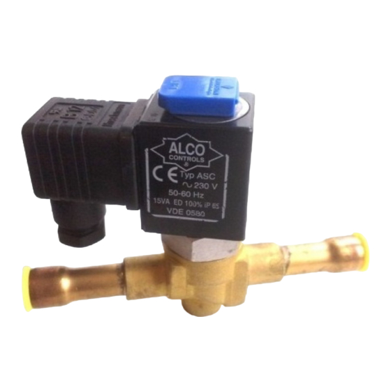
110RB/200RB/240RA Solenoid Valves are used for
shut-off purpose during operation on liquid, suction and
discharge line. Valve except 540RA are normally closed
types (NC), means when coil is de-energized valve is in
closed position. 540RA is normally open type (NO).
• Max. Operating Pressure PS: 31 bar;
• Max. Test Pressure PT: 34 bar; 540RA 20: 31 bar
• Operating Temperature Range TS: –40°C to 120°C
• Max. Ambient Temperature: -40 to 50°C
• Max. Transport Temperature: -40 to 70°C
• Max. body temperature:
• Valves with Tube Connection >32mm are CE
marked, except 540RA.
• Valves are in compliance with prEN 12284
• ASC Coil with IP 65 protection class (DIN 43650)
• Compatibility: CFC, HCFC, HFC, Mineral- and
Ester Lubricants
•
!
Safety instructions:
Read
installation
instructions
•
Failure to comply can result in device failure,
system damage or personal injury.
It is intended for use by persons having the
•
appropriate knowledge and skill. Before
attempting to install the solenoid valve make
sure pressure in system is brought to and
remains at atmospheric pressure.
•
Do not release any refrigerant into the
atmosphere.
Do not use any other fluid media without prior
•
approval of Alco Controls. Use of fluid not
listed could result in:
Change of Hazard Category of the product and
consequently change of conformity assessment
requirement for product in accordance with
European
Pressure
Equipment
97/23/EC.
In a severely contaminated system, avoid
•
breathing acid vapours and avoid contact with
skin from contaminated refrigerant / lubricants.
Failure to do so could result in skin injury.
WARNING: Do not use a solenoid valve as a
•
safety shut-off valve or for service purpose.
The solenoid coil should be fused in accordance
•
with local codes. Electrically ground the valve
body.
•
WARNING: Do not energize Coil unless it is
attached to the valve.
•
110RB/200RB/240RA are not released for use
with
flammable
refrigerants
hydrocarbon refrigerants and ammonia.
•
Before any service disconnect power supply
from coil.
Mounting location:
• 110RB/200RB/240RA should be installed as close
as possible to the device to be shut -off/controlled
by the valve.
• Allow sufficient clearance above the valve for
removal of Coil.
• Valves may be mounted in horizontal or vertical
lines (Fig. 1). Up-side down position is not
allowed and can cause mal-function (Fig. 2).
Document Nr.: A6.5.057 / 03
ALCO CONTROLS
Installation of Valve:
• Do not dent, bend, or use the enclosing tube as a
lever. A damaged enclosing tube may result in coil
burnout, inoperative valve or leakage.
• Direction of flow must match arrow on body.
• Before brazing clean tubing.
• Do not disassamble valve before brazing.
540RA 20: 28 bar
• Direct flame away from valve body (Fig. 3).
• Use an inert gas such as nitrogen to pass through
the valve to prevent copper oxide formation.
• The use of appropriate brazing material is required
(soft solder is not allowed). During brazing process
120°C
the cooling of the valve body is necessary to avoid
any internal damage(i.e. wet cloths). Do not
exceed max. body temperature of 120°C.
• Never use oxygen or flammable gases.
• Internal parts must be protected from foreign
material and moisture. ALCO filter-drier use in
liquid line and ALCO filter use in suction line is
recommended.
• Before energizing the valve be sure that the source
voltage and frequency matches that on the coil
label.
Installation of Coil:
thoroughly.
• Place coil over the enclosing tube. Coil may be
rotated 360° for ease of wiring.
• Press coil housing down firmly, secure (1) and
close (2) the coil retainer (Fig. 4).
Wiring With Cable Assem bly (Fig. 5)
• Color code: 1 = brown, 2 = blue, 3 = yellow/green
• Standard Cable (230V, 50Hz, 6 Amp max.)
Type
ASC-N15 804 570
ASC-N30 804 571
ASC-N60 804 572
ASC-L15 804 573
ASC-L30 804 574
ASC-L60 804 575
Directive
• Chopper Cable (26.5 V DC, 0.3 Amp max.) for
use with ASC 24 V / 50 - 60 Hz (801 062) only.
DS2-N15 804 620
DS2-N30 804 621
DS2-N60 804 622
DS2-L60 804 625
Wiring With Plug ASC-NM6
(Order nr. 804 576)
• Cable must be connected to terminal 1 and 2 on the
plug terminal box +
wired DIN-plug (Fig. 5) to the coil and tighten
screw with 0,1Nm.
such
as
Testing:
• Before Testing let the parts cool down to a
temperature <40°C.
• Cycle valve several times. A distinct click should
be heard each time the solenoid is energized.
• NOTE: ALCO solenoid valves are equipped with
a continous-duty coil, which when energized for an
extended period of time becomes hot. This is
normal.
Leakage test:
• After completion of installation, a pressure test
must be carried out as follows:
- According to EN378 for systems which must
comply
directive 97/23/EC
- To maximum working pressure of system for
other applications.
Replacement for A6.5.057 / 02
Operating Instructions
Solenoid Valve Series 110RB/200RB/240RA/540RA
Order Nr. Length
Temperature
1.5 m
-25 ... +80°C
3.0 m
-25 ... +80°C
6.0 m
-25 ... +80°C
1.5 m
-50 ... +80°C
3.0 m
-50 ... +80°C
6.0 m
-50 ... +80°C
1.5 m
-25 ... +80°C
3.0 m
-25 ... +80°C
6.0 m
-25 ... +80°C
6.0 m
-50 ... +80°C
(ground) . Connect pre-
with
European
pressure
equipment
Date: 02.02.2004
Warning:
1. Failure to do so could result in loss of refrigerant
and personal injury.
2. The pressure test must be conducted by skilled
persons with due respect regarding the danger
related to pressure.
Service:
• Before any service shut down system and disconnect
from power source.
• Fully depressurize Valve. After reducing pressure to
atmospheric the valve may be opened and internal
parts removed and replaced. Clean parts before re-
installation. Install parts in reverse sequence as
removed (Fig. 6-8).
Recommended Torque (Nm)
Type
Bolts
Encl. Tube
110 RB
-
10
200 RB
-
10
240 RA 8-16
9
10
240 RA 20
12
10
Maximum and min. operating pressure Differentials
Pressure Differential (bar)
Type
Max.
Max.
Operating
Operating
Differential
Differential
AC 50 Hz
AC 60Hz
110 RB
25
25
200 RB
25
21
240 RA
25
25
Partslist Fig. 6-8
Part-
Description
110RB 200RB 240RA 540RA
No.
1
Coil retainer
X
2
DIN plug
X
3
Coil
X
4
Enclosing Tube
X
5
Spring
X
6
Plunger
X
7
Gasket
X
8
Valve body
X
9
Screw+washer
X
10
Manual stem
11
Screw (4 pcs.)
12
Spring
13
Gasket
14
Diaphragm
15
Piston cpl.
16
Plug
Technical Data Coils
Power
ASC Coil
Voltage
Input
(V)
(W)
24V/50-60Hz
120V/50-60Hz
AC
10 W
230V/50-60Hz
12 V
24 V
DC
15 Watt
120 V
230 V
DWG Nr.: /PCN 860 592
GB
Manual Stem
-
34
34
34
Min.
operating
differential
50/60 Hz
0
0,05
0,05
X
X
X
X
X
X
X
X
X
X
X
X
X
X
X
X
X
X
X
X
X
X
X
X
X
X
X
X
X
X
X
X
X
X
X
X
X
X
Inrush
Holding
Current
Current
(I)
(I)
2
0,77
0,4
0,15
0,2
0,08
0,93
0,46
0,09
0,05
Advertisement
Table of Contents

Related Manuals for ALCO CONTROLS 110RB Series


Summary of Contents for ALCO CONTROLS 110RB Series
- Page 1 Do not use any other fluid media without prior • ASC-N15 804 570 1.5 m -25 … +80°C approval of Alco Controls. Use of fluid not ASC-N30 804 571 3.0 m -25 … +80°C listed could result in: ASC-N60 804 572 6.0 m...
- Page 2 ASC-N30 804 571 3.0 m -25 … +80°C lassen! ASC-N60 804 572 6.0 m -25 … +80°C Es dürfen nur von Alco Controls freigegebene • Kältemittel eingesetzt we rden. Die Verwendung ASC-L15 804 573 1.5 m -50 … +80°C ASC-L30 804 574 3.0 m...
- Page 3 • Presione la carcasa de la bobina firmemente hacia No utilice otros fluidos refrigerantes sin • 110 RB abajo, ajuste (1) y cierre (2) la pieza de retén consentimiento previo de Alco Controls. El uso 200 RB 0,05 (Figura 4). de refrigerantes no incluidos en la lista puede...
- Page 4 ALCO CONTROLS Istruzioni di Installazione Emerson Electric GmbH & Co Heerstr.111 - D 71332 Waiblingen Valvole Solenoidi Serie 110RB/200RB/240RA/540RA Tel.: 07151 509-0 - Fax.: -200 Informazioni Generali e Dati Tecnici: Installazione della valvola: Attenzione: Le valvole solenoidi della serie 110RB/200RB/240R A •...
- Page 5 ALCO CONTROLS Základní údaje Emerson Electric GmbH & Co Heerstr.111 - D 71332 Waiblingen Elektromagnetické ventily 110 RB, 200 RB,240 RA Tel.: 07151 509-221 - Fax.: -200 Elektromagnetické ventily rady 110 RB, 200 RB a • Ventil nemusí být rozebírán pred pájením zásahem do systému je nutno snížit tlak na...
- Page 6 ALCO CONTROLS 110 RB, 200 RB,240 RA Emerson Electric GmbH & Co Heerstr.111 - D 71332 Waiblingen Tel.: 07151 509-221 - Fax.: -200 Fig. 1 Fig. 2 110RB 200RB Fig. 4 Fig. 3 240RA / 540RA Fig. 5 Fig. 6 (110 RB) Fig.
Need help?
Do you have a question about the 110RB Series and is the answer not in the manual?
Questions and answers