
Summary of Contents for Elife SR Series
- Page 1 Low Profile Drive Size 1 - Size 2 - Size 3 Elife-Drive SR Series Application Reference Manual...
- Page 2 Fax: +39 0565 945726 email: support@elifeinternational.com This manual is copyrighted of Elife International. All rights are reserved. This manual must not be copied in whole or in part, nor transferred to any other media or language, without express written permission of Elife International.
-
Page 3: Table Of Contents
2 Installation and Wiring 2.1 Mounting Elife-Drive on-board ..... 2.2 Connections ....... . - Page 4 Elife-Drive I/O definitions for RS232 Mode ....22 Elife-Drive SR I/O definitions for Ev Car Mode ....23...
-
Page 5: Overview
Overview SR Elife-Drive is the family of drivers designed to drive the various types of low-voltage servomotors, specifically for use in battery powered devices. The compact form was made possible thanks to the high efficiency of the design, manufactured with state-of-art electronic components. - Page 6 Specification: Four Quadrant Regenerative Operation Space Vector Modulation Technology Sinusoidal and Trapezoidal Commutation Methods Programmable Gain Setting Fully Configurable Velocity and Position Limits On-the-fly Mode and Gain Set Switching Emergency Deceleration Ramp (Emergency) Input Safe Torque Off (STO) Input Programmable Input/Output: Six Digital Inputs Single Ended One 12-bit Analog Input 0 10 V...
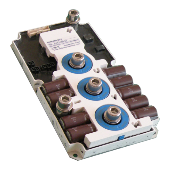
- Page 7 Most of information about your Elife-Drive - such as serial number, model, customer information, etc - can be found on a label located on the front of the Elife-Drive (see figure below). Some of these information might be requested when you contact the technical assistance.
-
Page 9: Installation And Wiring
Elife-Drive and the vehicle surface. Elife-Drive has a LED light on the front of the device that visually explains what the driver is doing (see Section 3.1), if you want it to be visible you should take this into consideration before choosing the location where your Elife-Drive will be mounted. - Page 10 A recommended installation method in order to ensure an effective heat Figure 2.1: dissipation between the Elife-Drive and the surface on which it will be placed. A thermal grease should be used between the Elife-Drive and the surface on which it will be placed. Installation and Wiring Chapter 2...
-
Page 11: Connections
Connections Elife-Drive on the front has different types of connectors: High Power Connections The three-phase alternating-current generated by Elife-Drive is supplied through the U,V,W terminals. are the positive and negative terminals to connect to your battery. You must connect an external fuse between the terminal and the positive battery terminal. -
Page 12: High Power Connections
High Power Connections High power connections are provided by: 3-phase supply terminals (U,V,W) and two terminals for battery connections (B+,B-). In order to connect correctly Elife-Drive, you should use the following instructions: Connect the the battery negative cable to the terminal. - Page 13 When connecting the high power cables, make sure that the feedback cable passes as far as possible from the power cables, possibly with a different path, this to avoid electromagnetic interference. Elife-Drive SR1 Series - High-power connections. Figure 2.2: Elife-Drive SR2 Series - High-power connections.
-
Page 14: Low Power Connections
2.2.2 Low Power Connections The low power logic control connections are provided by 4 female connectors. - The feedback interface connector - The Input/General Purpose connector - The Output connector - The Communications interface connector The pin’s description is given in Table below: Figure 2.5: Feedback Sensor Connections Installation and Wiring... - Page 15 Signal Command Connections Figure 2.6: Connections...
- Page 16 Alternative Feedback Sensor Connections Figure 2.7: Installation and Wiring Chapter 2...
- Page 17 The programming connections is provided by an 8 pins male connector and a DB9 female connector. The cable description is given in Table below: Program Connections Figure 2.8: Connections...
- Page 18 Installation and Wiring Chapter 2...
-
Page 19: Standard Wiring Diagrams
Standard Wiring Diagrams Standard wiring diagram to connect the Elife-Drive SR Series to your system - Figure 2.9: Multifeedback Standard Wiring Diagrams... - Page 20 Standard wiring diagram to connect the Elife-Drive SR Series to your system Figure 2.10: - Differential Fa-Coder Feedback Installation and Wiring Chapter 2...
- Page 21 flowing through the wire through the capacities in series with the wire internal phases of the motor. Alternative wiring diagram to connect the Ground Wire from the Elife-Drive Figure 2.11: to the Motor...
-
Page 22: Standalone Mode
2.3.1 Standalone Mode The Standalone mode is divided into two specific functions, traction motor control and steering motor control. The logic of this mode is to be able to drive the motor independently via the main inputs dedicated to the two specific functions. Other optional inputs can be used to extend the functionality of these operating modes (See Table 2.3). -
Page 23: Elife-Drive Sr I/O Definitions For Standalone Traction Mode
Elife-Drive SR I/O definitions for Standalone Traction Mode Table 2.3: ESCRIPTION Rising Edge Signal = Enable/Disable CRUISE Optional Active or Disable the Cruise Control if a Rising Edge Signal is detected High =Fast mode, Low = Slow mode. FAST/SLOW Optional... -
Page 24: Elife-Drive Sr I/O Definitions For Standalone Steering Mode
Elife-Drive SR I/O definitions for Standalone Steering Mode Table 2.4: ESCRIPTION OVERTRAVEL High = Active Overtravel for CW rotation, Optional Low = Inactive Overtravel OVERTRAVEL High = Active Overtravel for CCW rotation, Optional Low = Inactive Overtravel High = Clockwise,... -
Page 25: Canopen ® Mode
® For further information about CANopen protocol, please refer to CiA DSP402 ® protocol (version 3.0.1.15) and Elife-Drive CANopen Manual. A description of the inputs and outputs connections for this operating mode is shown in Table 2.5 ® In this operating mode is needed to set the correct CANopen parameters via ®... -
Page 26: Rs232 Mode
OUT4 SPEEDOMETER impulses/revolution - - - BRAKE OUT Optional It becomes active when the motor is stopped For further information, see Elife-Drive - RS232 Communication Protocol document Installation and Wiring Chapter 2... -
Page 27: Ev Car Mode
2.3.4 EV Car Mode Elife-Drive SR I/O definitions for Ev Car Mode Table 2.7: ESCRIPTION Rising Edge Signal = Enable/Disable CRUISE Optional Active or Disable the Cruise Control if a Rising Edge Signal is detected High = Sport mode, Low = Economy mode. - Page 28 When throttle is put to neutral position - before bridge activation - you can indicate if the brake should be locked or unlocked (HANDBRAKE input), the rotation direction (BACKWARD or FORWARD) and the speed mode (SPORT/ECONOMY input). The SPORT and ECONOMY modes are designed to meet two different purposes: ECONOMY mode This operating mode is specially designed in order to extend the battery life.
-
Page 29: Ev Bike Mode
2.3.5 EV Bike Mode Elife-Drive SR I/O definitions for Ev Bike Mode Table 2.8: ESCRIPTION Rising Edge Signal = Enable/Disable CRUISE Optional Active or Disable the Cruise Control if a Rising Edge Signal is detected High = Sport mode, Low = Economy mode. - Page 30 When throttle is put to neutral position - before bridge activation - you can indicate if the brake should be locked or unlocked (HANDBRAKE input), the rotation direction (BACKWARD or FORWARD) and the speed mode (SPORT/ECONOMY input). The SPORT and ECONOMY modes are designed to meet two different purposes: ECONOMY mode This operating mode is specially designed in order to extend the battery life.
-
Page 31: Monitoring Elife Drive
LED Diagnostics Elife-Drive has an LED light on the front of the device that visually explains what the driver is doing. Below is the explanation of the different LED’s status: Elife-Drive works correctly, motor is stopped... -
Page 32: Telemetry - Monitoring And Setting Of Data
® each selected operating mode (Standalone, CANopen , RS232, Bike EV, Car EV). Telemetry Panel displays a wide range of telemetry data and enables you to Figure 3.1: plot or log these data over time. Monitoring Elife Drive Chapter 3... -
Page 33: Motor Setting
3.2.1 Motor Setting Telemetry Motor Setting Telemetry Panel displays the Motor Parameters Figure 3.2: Telemetry - Monitoring and Setting of Data... -
Page 34: Feedback Setting
3.2.2 Feedback Setting Telemetry Motor Feedback Setting Telemetry Panel displays the Motor Fedback Parameters Figure 3.3: Monitoring Elife Drive Chapter 3... -
Page 35: System Parameters
3.2.3 System Parameters Telemetry System Parameters Telemetry Panel displays the System Parameters Figure 3.4: Telemetry - Monitoring and Setting of Data... -
Page 36: Configuration - Connection
3.2.4 Configuration - Connection Telemetry Connection Configuration Telemetry Panel Connection Configuration Figure 3.5: Monitoring Elife Drive Chapter 3... -
Page 37: Configuration - Standalone
3.2.5 Configuration - Standalone Telemetry Standalone Configuration Telemetry Panel displays the Standalone Configuration Figure 3.6: Telemetry - Monitoring and Setting of Data... -
Page 38: Configuration - Canopen
® 3.2.6 Configuration - CANopen ® Telemetry CANopen Configuration ® Telemetry Panel displays the CANopen Configuration Figure 3.7: Monitoring Elife Drive Chapter 3... -
Page 39: Configuration - Rs232
3.2.7 Configuration - RS232 Telemetry RS232 Configuration Telemetry Panel displays the RS232 Configuration Figure 3.8: Telemetry - Monitoring and Setting of Data... -
Page 40: Configuration - Ev Bike
3.2.8 Configuration - EV BIKE Telemetry EV Bike Configuration Telemetry Panel EV Bike Configuration Figure 3.9: Monitoring Elife Drive Chapter 3... -
Page 41: Configuration - Ev Car
3.2.9 Configuration - EV CAR Telemetry EV Car Configuration Telemetry Panel EV Car Configuration Figure 3.10: Telemetry - Monitoring and Setting of Data... -
Page 42: Id Drive
3.2.10 ID Drive Telemetry ID Drive Telemetry Panel displays the ID Drive Figure 3.11: Monitoring Elife Drive Chapter 3... -
Page 43: Adjustments
3.2.11 Adjustments Telemetry Adjustments Telemetry Panel Adjustments Figure 3.12: Telemetry - Monitoring and Setting of Data... -
Page 44: Log Status
3.2.12 Log Status Telemetry Log Status Telemetry Panel displays the Log Status Figure 3.13: Monitoring Elife Drive Chapter 3... - Page 45 Telemetry - Monitoring and Setting of Data...
- Page 46 © Elife International S.r.l. - 2021 https://www.elifeinternational.com...
Need help?
Do you have a question about the SR Series and is the answer not in the manual?
Questions and answers