Table of Contents
Advertisement
Quick Links
Advertisement
Table of Contents

Summary of Contents for Masalta MSP Series
- Page 1 INSTRUCTION MANUAL SUBMERSIBLE PUMP ( FLEXIBLE SHAFT PUMP) MSP SERIES WARNING...
-
Page 2: Table Of Contents
CONTENTS SAFETY INSTRUCTIONS …………………1 SERVICE & MAINTENANCE…..………7-8 HEALTH & SAFETY…………….…..………2 TECHNICAL DATA …..………..…………8-9 TRANSPORTATION……………….….…….3 TROUBLESHOOTING.………..…………9-10 LABELS………………….….……….….……4 WARRANTY ……..…………..……..……10 FUNCTIONAL DESCRIPTION……………5-6 MAINTENANCE RECORD……..…………11 OPERATION …...………...………...……6-7 EC DECLARATION…………….…………..12 SAFETY INSTRUCTIONS For your own personal protection and for the safety of those around you, please read and ensure you fully understand the following safety information. -
Page 3: Health & Safety
Do not change the preset engine speed. This could cause engine damage. Check for fuel leaks before running the machine. Do wear working-gloves, safety glasses and protecting clothing during refueling. Make sure that there is sufficient ventilation during refueling. ... -
Page 4: Transportation
TRANSPORTATION Switching off the unit Before you transport the unit, it must be switched off, and the engine must be given sufficient time to cool down. Lifting When lifting the unit, observe the following instructions: Designate a skilled person to guide you for the lifting procedure. ... -
Page 5: Labels
LABELS Your unit has adhesive labels containing the most important instructions and safety information. Make sure that all the labels are kept legible. Replace any missing or illegible labels. Label Meaning DANGER! Engines emit carbon monoxide; operate only in well-ventilated area. -
Page 6: Functional Description
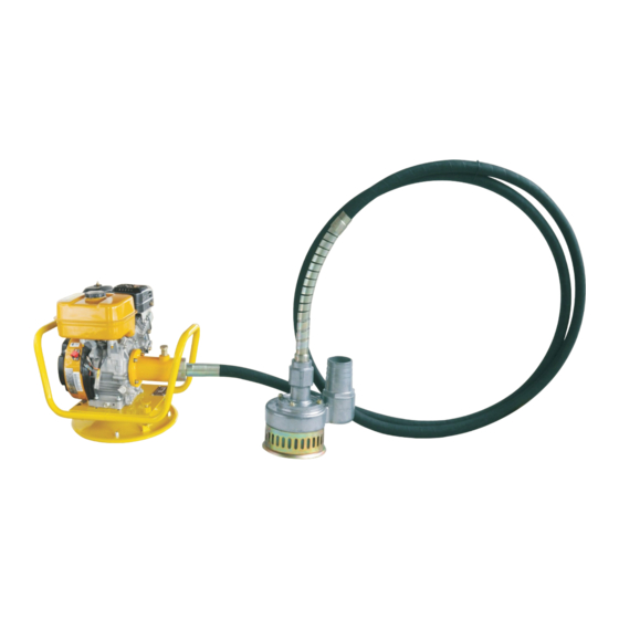
FUNCTIONAL DESCRIPTION The submersible pump consists of the components Drive unit Pump head Flexible shaft Item Description Item Description Drive Unit MVDR Pressure Connection Connection to Drive Unit Suction Strainer Flexible Shaft Flexible Shaft Connection Spring protection Connection to Pump Head Optional Drive Unit --- MVDS &... -
Page 7: Operation
Functionality (schematic diagram) Item Description Item Description Drive Pump Head Hose protection Hose Clamp (optional) Protective hose with flexibleshaft Pressure hose (optional) The drive drives the pump head by means of a flexible shaft. The pump head sucks water through the suction strainer and pumps it through the pressure hose. -
Page 8: Service & Maintenance
Fuel level – the tank should be at least half full. Oil level – the oil level must be between the lower and upper marks. Air filter – replace any damaged parts. Starting up Prior to operating the submersible pump, the drive engine should have the correct operating temperature (warm up for 2-3 minutes). - Page 9 Maintenance schedule Daily After the Weekly or Monthly Annually before first every or every or every operation 20 hours 25 hours 100 hours 300 hours Check the fuel: - fuel level of tank - tank for leaks - lines for leaks Check the oil level of the ...
-
Page 10: Technical Data
TECHNICAL DATA Drive Unit MVDR-1 MVDR-3 MVDR-4 Model MVDS-1 MVDS-3 MVDS-4 Petrol, Robin Petrol, Honda Electric Engine Type Diesel, 170 EX17 GX160 Motor Power kw 1.1/1.5 21 (46) 21 (46) Weight kg (lb) 31 (68) Pump Head with Flexible Shaft MSP3 Model MSP2... -
Page 11: Warranty
Pump head Malfunction Cause Remedy Abnormal noises Grease used up Replace grease Ball bearing defective Have the ball bearing replaced Flexible shaft damaged Replace the flexible shaft Protective hose damaged Replace the protective hose Low delivery volume Pump housing, impeller, main Have the part replaced shaft or oil seal damaged or worn... -
Page 12: Maintenance Record
MAINTENANCE RECORD Preventative Maintenance and Routine Service Plan This Vibrating Screed Screed has been assembled with care and will provide years of service. Preventative maintenance and routine service are essential to the long life of your Vibrating Screed. After reading through this manual thoroughly, you will find that you can do some of the regular maintenance yourself. -
Page 13: Ec Declaration
CE-KONFORMIT.TSERKL.RUNG DECLARACIÓN DE CONFORMIDAD DE LA CE DÉCLARATION DE CONFORMITÉ C.E. MASALTA ENGINEERING CO., LTD Weisi Road, Baohe Industrial Estate, HeFei 230051, China hereby certifies that the construction equipment specified hereunder / bescheinigt, da. das Bauger.t / certifica que la máquina de construcción / atteste que le matériel :... - Page 14 Distributed By MASALTA ENGINEERING CO., LTD Add: Weisi Road, Baohe Industrial Estate, Hefei, China Tel: 86-551-4846600, 4846601 Fax: 86-551-4846616 E-mail: sales@masalta.com.cn, masalta@mail.hf.ah.cn, Http://www.masalta.com.cn Version: 01/12/01...
Need help?
Do you have a question about the MSP Series and is the answer not in the manual?
Questions and answers