Table of Contents
Advertisement
Quick Links
User manual
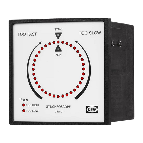
Check synchroscope type CSQ-3
4189340263L (UK)
•
Multi function, precision LED synchronoscope
•
Easy push-button programming of all set points
•
Very high user safety
•
High immunity to harmonic distortion
•
Dead bus functionality
•
Special version for marine applications
DEIF A/S
Frisenborgvej 33, DK-7800 Skive
Denmark
Tel.:
(+45) 9614 9614
Fax:
(+45) 9614 9615
E-mail: deif@deif.com
Advertisement
Table of Contents

Summary of Contents for Deif CSQ-3
- Page 1 User manual Check synchroscope type CSQ-3 4189340263L (UK) • Multi function, precision LED synchronoscope • Easy push-button programming of all set points • Very high user safety • High immunity to harmonic distortion • Dead bus functionality • Special version for marine applications DEIF A/S Tel.:...
-
Page 2: Table Of Contents
Appendix 1: Setting and parameters for synchronising ........16 Settings ........................16 Guidelines for setting of the CSQ-3 ............... 18 Visual representation of the parameters ............... 18 Page 2 of 21 Tel.: (+45) 9614 9614 • Fax: (+45) 9614 9615 • E-mail: deif@deif.com... -
Page 3: Warnings, Legal Information And Notes To Ce-Marking And Ul Listing
This covers all environment types where the CSQ-3 can normally be used. The CSQ-3 is CE-marked with respect to the low-voltage directive for up to 600V phase to ground voltage, installation category (overvoltage category) III and pollution degree 2. - Page 4 (overfrequency synchronising). Note: This function is not active with t set to ∞. Page 4 of 21 Tel.: (+45) 9614 9614 • Fax: (+45) 9614 9615 • E-mail: deif@deif.com...
- Page 5 LED (SYNC) will be lit, when the busbar voltage is below the dead busbar preset level and the GEN voltage exceeds 80% of nominal value. Please notice that when the voltage on the net has been restored, the CSQ-3 will remain in the dead bus function for a period of 5 seconds.
-
Page 6: Operation Of Display, Push-Buttons And Leds
Mode ∆ The CSQ-3 can be operated in two different modes: ‘Normal mode’ and ‘setting mode’. Normal mode is used to display measuring values, and setting mode is used to view the settings or change them to the desired functionality. -
Page 7: Leds
User manual, Check synchroscope CSQ-3 3.1 LEDs The CSQ-3 has the following LEDs on the fronts showing different operating information. LEDs on primary front (normal mode): Colour Function Circle The lit LED in the circle shows the phase difference between GEN and BUSBAR SYNC. -
Page 8: Settings
3.2 Settings MODE: NORMAL U max. U min. SET/VIEW SET/VIEW SET/VIEW tr = SET/VIEW SET/ACTIVATE DEAD-BUS SAVE automatically NORMAL Page 8 of 21 Tel.: (+45) 9614 9614 • Fax: (+45) 9614 9615 • E-mail: deif@deif.com... - Page 9 User manual, Check synchroscope CSQ-3 Operation The operation occurs via the secondary foil accessible when the primary foil/front frame is removed. The operation occurs by means of 3 push-buttons: Mode (toggle), up arrow (▲) and down arrow (▼). Control of settings The mode button is held down for about 2-3 seconds to obtain the setting mode.
-
Page 10: Terminal List
Only on marine version: System status circuit off + open collector = failure - open collector Rear view of the unit: Land version Marine version Page 10 of 21 Tel.: (+45) 9614 9614 • Fax: (+45) 9614 9615 • E-mail: deif@deif.com... -
Page 11: Wiring Diagrams
User manual, Check synchroscope CSQ-3 5. Wiring diagrams 5.1 AC input connections When ordering the CSQ-3, the correct range of voltage inputs must be specified. They must be connected as shown below (unused terminals are not shown). 5.1.1 Connection diagram... -
Page 12: Commissioning
Inductive loads: AC15: 3A, 250V AC DC13: 3A, 24V DC (UL/cUL: Resistive load only) Mechanical life: 2 x 10 Electrical life: 1 x 10 (nominal value) Page 12 of 21 Tel.: (+45) 9614 9614 • Fax: (+45) 9614 9615 • E-mail: deif@deif.com... - Page 13 User manual, Check synchroscope CSQ-3 Optocoupler output: System status off = failure NpN optocoupler output Max. 40V, 10mA 2 wires AWG 20 (red/black) 30 mm length (Only in marine version) Temperature: -10…55°C (nominal) -25…70°C (operating) -40…70°C (storage) Temperature drift: Set points: Max.
- Page 14 Dimensions: Please see drawing in section 8 Panel cut-out: 92 x 92 ±1 mm Weight: < 0.40 kg Page 14 of 21 Tel.: (+45) 9614 9614 • Fax: (+45) 9614 9615 • E-mail: deif@deif.com...
-
Page 15: Dimensions
User manual, Check synchroscope CSQ-3 8. Dimensions All dimensions in mm. 9. Order specifications Input voltage and type must be specified when ordering the CSQ-3. Order specification for the CSQ-3 consists of the following: CSQ-3 - U - type where U... -
Page 16: Appendix 1: Setting And Parameters For Synchronising
SYNC. The regulating range is 0...1 sec. in steps of 0.1 sec. is only activated if t is set to ∞. Page 16 of 21 Tel.: (+45) 9614 9614 • Fax: (+45) 9614 9615 • E-mail: deif@deif.com... - Page 17 The scale 10-20-30-40 should therefore be considered more as a 4 level noise suppression than as an accurate measuring setting. Please notice that when the voltage on the net has been restored, the CSQ-3 will remain in the dead bus function for a period of 5 seconds.
-
Page 18: Guidelines For Setting Of The Csq-3
10 + 10 ∆f = ∆f = = 0.278Hz 360 x 0.2 360 x t Synchronising relay pulse will not be emitted if ∆f exceeds 0.278Hz. Page 18 of 21 Tel.: (+45) 9614 9614 • Fax: (+45) 9614 9615 • E-mail: deif@deif.com... - Page 19 The same as examples 1 and 2 but with a slip frequency of 0.3Hz = 108°/sec. At t 0.2 sec. the phase will change 21.6°. As the ∆ϕ window is set to ±10°, the CSQ-3 will calculate that there is no longer space for a t pulse of 0.2 sec.
- Page 20 (∆f) of 0.1Hz = 36°/sec. and t = 0.4 sec. the phase changes 14.4° during the 0.4 sec. If ∆ϕ is set to ±10° the CSQ-3 will calculate that there is space for t . With this setting the synchronising error will be identical with the synchronising error in example 1 (-2.8°) as the breaker closing time is the same (0.2 sec.).
- Page 21 ∆f of 0.05Hz. Function in particular situations: In connection with test “on desk” the CSQ-3 is normally connected to the same supply point so that frequency and phase are completely identical on the generator input and the busbar input. At this test form the following must be noticed: The first time the CSQ-3 is connected, synchronising pulse is emitted whether the ∆ϕ...
Need help?
Do you have a question about the CSQ-3 and is the answer not in the manual?
Questions and answers