
Summary of Contents for Vitalcare 506N3 Series
- Page 1 VitalCare 506N3 Series Patient Monitor Service Manual Cat. No. 1446 Part No. 39178B101 Date 08/07 Revision 1...
-
Page 2: Copyright
Nellcor Puritan Bennett Inc. ® ® FILAC and FasTemp are registered trademarks of TYCO Healthcare. ® TurboTemp is a registered trademark of Cardinal Health, Inc. Page ii VitalCare 506N3 Series Service Manual Criticare Systems, Inc. -
Page 3: Table Of Contents
Safety ....................1-18 Software Error Related Hazard Mediation ......1-19 Potential Interference..............1-19 Leakage Current ..............1-19 Voltage Fluctuations ...............1-20 Defibrillation, HF, and Electronic Device Protection ....1-20 Biocompatibility...............1-20 Latex Content .................1-20 DEHP Content ................1-20 Page iii Criticare Systems, Inc. VitalCare 506N3 Series Service Manual... - Page 4 NIBP Tone................2-15 Average ................ 2-15 Printer Setup Menu................. 2-16 On NIBP ................. 2-16 On Alarm ................2-16 Interval ................... 2-16 Print To................... 2-16 Serial ..................2-16 Baud Rate ................2-16 Page iv VitalCare 506N3 Series Service Manual Criticare Systems, Inc.
- Page 5 Printer Module ................3-4 Block Diagram ...................3-5 Section 4 — Cleaning and Disinfecting Cleaning and Disinfecting..............4-1 Blood Pressure Cuffs..............4-1 DOX Pulse Oximeter Sensors ..........4-2 OxiMax Pulse Oximeter Sensors..........4-2 Temperature Probes..............4-4 Accidental Wetting................4-5 Page v Criticare Systems, Inc. VitalCare 506N3 Series Service Manual...
- Page 6 Pinout Chart ................6-3 Procedure................. 6-3 DOX SpO Performance Testing............6-4 Programming the SmartSat Analyzer........6-4 Test Procedure................. 6-4 Nellcor SpO Performance Testing ..........6-5 Programming the SmartSat Analyzer........6-5 Test Procedure................. 6-5 Page vi VitalCare 506N3 Series Service Manual Criticare Systems, Inc.
- Page 7 Replace LCD and LED Display Boards ........7-31 Replace Membrane ..............7-35 Chassis Service/Pump Disassembly ..........7-39 Replace ComfortCuff NIBP Module ........7-41 Replace Power Supply ............7-42 Completion of Service ..............7-43 Section 8 — Troubleshooting Troubleshooting Guide ..............8-1 Page vii Criticare Systems, Inc. VitalCare 506N3 Series Service Manual...
- Page 8 Appendix A — Main Board Upgrades Overview................... A-1 Battery Disconnect Warning Inducator........A-1 Backward Compatability ..............A-1 Upgrading the Main Board..............A-2 Removing the old Main Board..........A-2 Installing the new Main Board ..........A-4 Page viii VitalCare 506N3 Series Service Manual Criticare Systems, Inc.
-
Page 9: Warranty
Criticare Systems, Inc., or the 506N3 Series monitors are not used in accordance with the instructions for use, or the electrical installation of the relevant room does not comply with... -
Page 10: Service Return Policy
If a discrepancy to these inspection items is observed, do not use the instrument and immediately report the discrepancy to the CSI Service Department. Page x VitalCare 506N3 Series Service Manual Criticare Systems, Inc. -
Page 11: Ec Declaration
9 Clarendon Place Leamington Spa Warwickshire CV 32 5QP T: 0044 (0) 1926 886688 F: 0044 (0) 1926 885588 For the Attention of: Ref. 45 (or) Mr. L. A. Heizler Criticare Systems, Inc. VitalCare 506N3 Series Service Manual Page xi... -
Page 13: Section 1 - Introduction
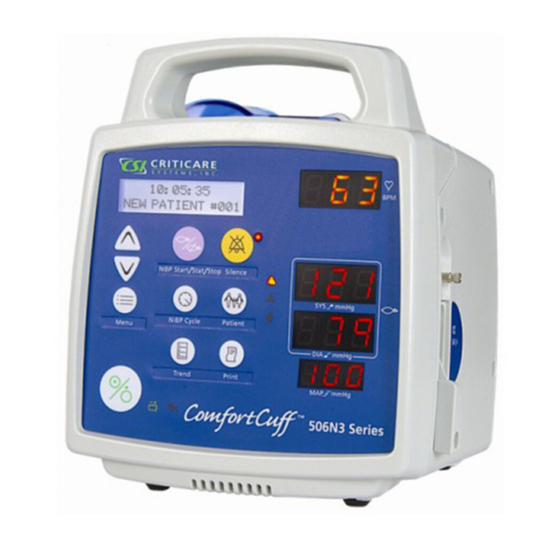
Section 1 — Introduction Description The 506N3 Series patient monitor is a compact vital signs monitor that measures heart rate and non-invasive blood pressure (NIBP). Heart rate measurement is determined primarily by the plethysmographic waveform. For units without the oximeter module,... -
Page 14: Intended Use
This equipment is intended for use only by qualified medical providers in conjunction with established medical protocols. All models in the 506N3 series are designed to monitor physiological parameters of patients, providing the health care provider with physiological data, alarms, and trend records. -
Page 15: Non-Invasive Blood Pressure (Nibp)
Section 1 —Introduction Non-Invasive Blood The 506N3 Series monitor uses ComfortCuff technology to ™ determine non-invasive blood pressure by means of oscillometry. The Pressure (NIBP) oscillometric method detects volume displacements within the artery and senses pressure variations within the blood pressure cuff during inflation. -
Page 16: Cuff Inflation And Pressure Protection
Cuff deflates rapidly after monitor determines systolic pressure Time Pulse Waveform (Measured from B.P. Cuff Pressure Fluctuation) Systolic Diastolic Mean Pressure Pressure Pressure Figure 1-1: NIBP Cuff Pressure and Pulse over Time Page 1-4 VitalCare 506N3 Series Service Manual Criticare Systems, Inc. -
Page 17: Heart Rate
The monitor continues to look for valid SpO based heart rate measurements and attempts a second NIBP measurement if the first attempt fails. Pulse Oximetry The 506N3 Series monitor is available with Digital Oximetry (DOX ™ technology to measure blood oxygen saturation (SpO Measurement (SpO Definition Hemoglobin exists in the blood in several forms: •... - Page 18 The accuracy specifications of this device will not be met with high concentrations of dyshemoglobins. Significant concentrations of carboxyhemoglobin results in a higher displayed value than is actually present in the patient. Page 1-6 VitalCare 506N3 Series Service Manual Criticare Systems, Inc.
-
Page 19: Method
Section 1 —Introduction Nellcor Pulse Oximetry ® The 506N3 Series monitor is also available with Nellcor OxiMax technology to measure blood oxygen saturation (SpO Measurement (SpO Definition The Nellcor OxiMax uses pulse oximetry to measure functional oxygen saturation in the blood. Pulse oximetry works by applying an OxiMax sensor to a pulsating arteriolar vascular bed, such as a finger or toe. -
Page 20: Automatic Calibration
= x 100 100 - (%carboxyhemoglobin + % methemoglobin ) Page 1-8 VitalCare 506N3 Series Service Manual Criticare Systems, Inc. -
Page 21: Measured Versus Calculated Saturation
See “Figure 1-2: Oxyhemoglobin Dissociation Curve”. * pH * Temperature * PCO * 2,3-DPG * Fetal Hb * pH * Temperature * PCO * 2,3-DPG (mmHg) Figure 1-2: Oxyhemoglobin Dissociation Curve Criticare Systems, Inc. VitalCare 506N3 Series Service Manual Page 1-9... -
Page 22: Temperature
Section 1 —Introduction Temperature The 506N3 Series monitor is available with an optional temperature ® ® module utilizing either FILAC FasTemp or Alaris™ (IVAC) ® TurboTemp technology. Two modes are available: Predictive and Continuous. Predictive Mode The default mode is Predictive Mode. This allows the thermometer to predict the end point that the thermistor would reach if it were left in the mouth until it reached mouth temperature. -
Page 23: Continuous Mode
±0.1 °C (±0.2 °F) in the continuous operation mode using a calibrated water bath. The accuracy range of 98.0 °F to 102.0 °F meets the range specified in ASTM specification #1112, Table 1. Criticare Systems, Inc. VitalCare 506N3 Series Service Manual Page 1-11... - Page 24 (pulse tone pitch varies with SpO Method: Dual wavelength LED Operation: Continuous Use Motion Artifact Rejection: Pulse Rate Range: 20 to 300 bpm Pulse Rate Accuracy: ±2 bpm (20 to 250 bpm) Page 1-12 VitalCare 506N3 Series Service Manual Criticare Systems, Inc.
- Page 25 26.0° C to 41.1° C (80.0° F to 106.0° F) Response Time: 10 sec. typical (oral measurements) Continuous Mode Accuracy: ±0.1° C, ±0.2° F full range Display Resolution: ±0.1° C (±0.1° F) Criticare Systems, Inc. VitalCare 506N3 Series Service Manual Page 1-13...
- Page 26 Interval Print: 1, 2, 5, 10, 15, 30, 60 minutes; 2, 4, 8, 12, 24 hours Data Types: NIBP, SpO , Pulse, Temperature Selectable Print Types: Print on NIBP and/or alarm Page 1-14 VitalCare 506N3 Series Service Manual Criticare Systems, Inc.
- Page 27 Medical Device: Class II Equipment Electrical Protection: Class I Equipment Degree of Protection: Type CF, Defibrillator-Proof Protection against ingress: IPX1 rating, Drip-Proof Equipment All specifications are subject to change without notice. Criticare Systems, Inc. VitalCare 506N3 Series Service Manual Page 1-15...
-
Page 28: Symbols
(WEEE Directive 2002/96/EEC) Alternating Current (AC) Fuse Technical Support Phone Number Non-Invasive Blood Pressure, Connection Systolic blood pressure Mean blood pressure Diastolic blood pressure Temperature Monitoring Sensor Monitoring, Connection Heart Rate Page 1-16 VitalCare 506N3 Series Service Manual Criticare Systems, Inc. - Page 29 Section 1 —Introduction Symbol Definition Communication Transmit/Receive Port Not a Sensor Connection Criticare Systems, Inc. VitalCare 506N3 Series Service Manual Page 1-17...
-
Page 30: Safety
• Changes or modifications not expressly approved by Criticare Systems, Inc., may void the user's authority to operate the equipment and may also void the warranty. Page 1-18 VitalCare 506N3 Series Service Manual Criticare Systems, Inc. -
Page 31: Software Error Related Hazard Mediation
Standards include the International Electrotechnical Commission (IEC) 60101-1, 1st edition, 2003 Part 1. A hazard caused by the summation of leakage currents is possible, when several pieces of equipment are interconnected. Criticare Systems, Inc. VitalCare 506N3 Series Service Manual Page 1-19... -
Page 32: Voltage Fluctuations
All Criticare Systems, Inc., products currently shipping are free of DBP and DEHP in any areas that would be intended for patient contact with blood, mucous membranes, or continuous skin/tissue contact. Page 1-20 VitalCare 506N3 Series Service Manual Criticare Systems, Inc. -
Page 33: Section 2 - Service Menus
NIBP Calibration Mode. These service software tools allow downloading of software upgrades for the 506N3 Series operating system and for calibration of the NIBP module in the field. To exit the SERVICE DISPLAY power cycle the 506N3 Series monitor. Service Mode WARNING •... -
Page 34: Secondary Service Displays
Wait 5-10 seconds before entering to allow the processor to acknowledge the revisions. If a revision does not show, either that module is not present in the device or the processor is not functioning correctly. Page 2-2 VitalCare 506N3 Series Service Manual Criticare Systems, Inc. - Page 35 NIBP SEAL Tests NIBP pressure seals and transducer. Choices are OFF and ON. Press the MENU key with ON displayed to begin the test sequence with a new prompt message. Criticare Systems, Inc. VitalCare 506N3 Series Service Manual Page 2-3...
-
Page 36: Self Tests
Press the MENU key with DONE displayed to re-enter the LED TEST. Press an ARROW key to replace the message DONE to OFF to prevent accidental restarting of the LED TEST. Page 2-4 VitalCare 506N3 Series Service Manual Criticare Systems, Inc. - Page 37 PRINT TEST. NOTE: Monitors built prior to 2007 have an additional alternate print test built in to the firmware which is no longer applicable. Criticare Systems, Inc. VitalCare 506N3 Series Service Manual Page 2-5...
-
Page 38: Nibp Calibration Mode
To enter the NIBP Calibration mode: 1. Press the POWER key and the NIBP/START/STAT/STOP key at the same time. 2. The 506N3 Series monitor attempts to connect to extended NIBP calibration tools through the external serial port, identifying itself as a 506N3 Series monitor. -
Page 39: Lcd Text Display
If there has been no keypad activity for 20 seconds the menu clears. The LCD text window returns to reporting messages or goes blank if no messages exist. Criticare Systems, Inc. VitalCare 506N3 Series Service Manual Page 2-7... -
Page 40: Factory Defaults
LN3 Series: F, N N (LN3 Series) Temperature Mode Pred, Cont Pred † Degrees F/C † The monitor returns to this setting on power up. Not available prior to Revision 1.5A Main Software. Page 2-8 VitalCare 506N3 Series Service Manual Criticare Systems, Inc. -
Page 41: Printer Setup
NOTE: The NIBP CYCLE menu is accessed using the NIBP CYCLE key located on the front panel. All other default settings are accessed using the MENU key with the UP/DOWN keys. Criticare Systems, Inc. VitalCare 506N3 Series Service Manual Page 2-9... -
Page 42: Trend Menu
USER default settings. LOW SPO2 returns to a default value of 85% if the current setting is below 85%. 5. Verify all settings are set correctly. Page 2-10 VitalCare 506N3 Series Service Manual Criticare Systems, Inc. -
Page 43: Power Up In Service Mode
4. Press the MENU key to change the default. The arrow in that display line should point to the right. 5. Press the UP or DOWN arrow keys until USer appears. Criticare Systems, Inc. VitalCare 506N3 Series Service Manual Page 2-11... - Page 44 YES appears. 11.Press the MENU key. The message STORE USER<-DONE should appear. 12.Press and hold the MENU key to exit the DEFAULT SETUPS menu. 13.Power cycle monitor to exit Service mode. Page 2-12 VitalCare 506N3 Series Service Manual Criticare Systems, Inc.
-
Page 45: Alarm Menu
Pulse Volume Sets the volume for the audible pulse tone from Off, and 1 through 10, with 1 being the softest and 10 the loudest. The factory default value is Off. Criticare Systems, Inc. VitalCare 506N3 Series Service Manual Page 2-13... -
Page 46: High Pulse
25 to 125 mmHg and Off. The factory default value is 50 for Adult and Pediatric modes and 40 for Neonate mode for hospital defaults. The default value for all modes is Off for Alternate Care defaults. Page 2-14 VitalCare 506N3 Series Service Manual Criticare Systems, Inc. -
Page 47: High Temperature
9, 12,15,18, and 21 seconds. The factory default value is 12 seconds. For monitors with Nellcor SpO , the available averaging times are F (Fast) and N (Normal). The factory default value is N. Criticare Systems, Inc. VitalCare 506N3 Series Service Manual Page 2-15... -
Page 48: Printer Setup Menu
2, 4, 8, 12, or 24 hours, and OFF. The factory default is OFF. Print To Sets the output device of the monitor. Use Printer for the internal printer of the 506N3 Series. External printing and downloading is available using the Serial setting. Choose OFF to disable printing. Serial Sets the data format for the external serial port (for sending data to an external device). -
Page 49: Configuration Menu
Enable MAP Enables (ON) or disables (OFF) MAP display on the monitor. Also removes MAP from the headers and printouts when set to OFF. The factory default is ON. Criticare Systems, Inc. VitalCare 506N3 Series Service Manual Page 2-17... -
Page 50: International Configuration Settings
4 H. Patient Button Settings Press the PATIENT button to select the patient mode. Choices are Adult, Pediatric, and Neonatal. The factory default setting is Adult. Page 2-18 VitalCare 506N3 Series Service Manual Criticare Systems, Inc. -
Page 51: Section 3 - Theory Of Operation
Section 3 — Theory of Operation System Architecture The 506N3 Series circuitry consists of a Main Board, Display Board, LCD Module, SpO Module, and NIBP module. Units with temperature also have a Temperature module with an Isolation Module. Units with an internal printer have a Printer Module. Units... -
Page 52: Module Architecture
Module Architecture Main Board The hardware design of the 506N3 Series monitor relies on multiple serial communication channels wherein the Main Board functions as (pn 91384A001/2/3) the hub. Signal and display processing is off-loaded to the various vital signs technology modules, the Display Board, and the LCD Module. -
Page 53: Nibp Module
(pn 91387A001) arrangement. The Nellcor Carrier board provides electrical isolation of 1500VAC minimum through power and serial interface connections. The Nellcor sensor connector is mounted directly onto the Carrier Board. Criticare Systems, Inc. VitalCare 506N3 Series Service Manual Page 3-3... -
Page 54: Temperature Modules
Section 3 —Theory of Operation Temperature Modules The 506N3 Series offers a choice of two leading predictive temperature technologies: FILAC FasTemp™ and Alaris ® TurboTemp . Each operate in a similar manner. Patient temperature sensing is accomplished by utilizing a negative-temperature coefficient (NTC) thermistor located in the probe tip. -
Page 55: Block Diagram
Speaker MAIN NIBP Module BOARD (91384A001/2/3) PAPER FEED Not Used 12VDC Input button LCD Connector Front Membrane Not Used RS232 Battery Communication Figure 3-1: 506N3 Series Board Interconnect Block Diagram Criticare Systems, Inc. VitalCare 506N3 Series Service Manual Page 3-5... -
Page 57: Section 4 - Cleaning And Disinfecting
Feed the inflation tube back through the hole and then pull out the cloth flap. Flap Figure 4-1: Remove the Inflation Bag Criticare Systems, Inc. VitalCare 506N3 Series Service Manual Page 4-1... -
Page 58: Dox Pulse Oximeter Sensors
Wipe all surfaces of the sensor and the cable with this gauze pad. 2. Saturate another clean, dry gauze pad with sterile or distilled water. Wipe all surfaces of the sensor and cable with this gauze pad. Page 4-2 VitalCare 506N3 Series Service Manual Criticare Systems, Inc. - Page 59 Wipe all surfaces of the sensor and cable with this gauze pad. 3. Dry the sensor and cable by wiping all surfaces with a clean, dry gauze pad. CAUTION • Do not sterilize by irradiation, steam, or ethylene oxide (EtO). Criticare Systems, Inc. VitalCare 506N3 Series Service Manual Page 4-3...
-
Page 60: Temperature Probes
Slippage caused by loss of spring tension may result in inaccurate sensor readings. Temperature Probes To clean the probe tip, use a damp cloth with diluted detergent. Page 4-4 VitalCare 506N3 Series Service Manual Criticare Systems, Inc. -
Page 61: Accidental Wetting
Time is critical! The longer any liquid remains in the monitor, the more damage it can do. It is important to service the monitor immediately after any liquid is spilled into it. Criticare Systems, Inc. VitalCare 506N3 Series Service Manual Page 4-5... -
Page 63: Section 5 - Preventative Maintenance
International Customer Service: (262) 798-8282 Calibration No periodic calibration of the monitor is necessary. It is recommended to perform an NIBP calibration verification as part of the annual safety testing. Criticare Systems, Inc. VitalCare 506N3 Series Service Manual Page 5-1... -
Page 64: Serviceable Components
• The used battery is a potential environmental hazard and must be disposed of properly. Dispose the old battery in accordance with local and federal laws. Do not incinerate. Page 5-2 VitalCare 506N3 Series Service Manual Criticare Systems, Inc. - Page 65 Figure 5-1: Remove Screws 3. Remove the battery (pn 80518B001) from the monitor. Figure 5-2: Remove Battery 4. Label and remove the cables connected to the battery. NOTE: Printing faces inward. Criticare Systems, Inc. VitalCare 506N3 Series Service Manual Page 5-3...
- Page 66 2. Gently pull the fuse cover(s) with fuse(s) out of the fuse assembly. Fuse Covers Fuses Fuse Wells Figure 5-4: 506N3 Series Fuses 3. Gently pull the fuse(s) out of the fuse cover(s). 4. Reassemble in reverse order. Page 5-4 VitalCare 506N3 Series Service Manual Criticare Systems, Inc.
-
Page 67: Annual Testing
System Check (LED test) b. Speaker Performance and Alarm Verification c. Power Supply Performance d. Printer Performance 3. Vital Sign Modules Verifications a. NIBP b. Oximeter (SpO )--DOX or Nellcor c. Temperature Criticare Systems, Inc. VitalCare 506N3 Series Service Manual Page 5-5... -
Page 68: Equipment And Tools
FasTemp), • Alaris Temp Probe (units with TurboTemp), and • Alaris No. TE 1811 Probe Simulator (units with TurboTemp). To order Alaris Probe Simulator, contact Cardinal Health/Alaris Customer Service. 1-800-482-4822. Page 5-6 VitalCare 506N3 Series Service Manual Criticare Systems, Inc. -
Page 69: Test Fixtures
Section 5 —Preventative Maintenance Test Fixtures DOX S 02 HI-POT TEST FIXTURE DOX S O2 LEAKAGE TEST FIXTURE NELLCOR HI-POT TEST FIXTURE Criticare Systems, Inc. VitalCare 506N3 Series Service Manual Page 5-7... - Page 70 Section 5 —Preventative Maintenance NELLCOR LEAKAGE TEST FIXTURE EMP HI-POT TEST FIXTURE EMP LEAKAGE TEST FIXTURE Page 5-8 VitalCare 506N3 Series Service Manual Criticare Systems, Inc.
- Page 71 Section 5 —Preventative Maintenance URBO EMP HI-POT TEST FIXTURE URBO EMP LEAKAGE TEST FIXTURE Criticare Systems, Inc. VitalCare 506N3 Series Service Manual Page 5-9...
-
Page 72: Electrical Safety Tests
• Arc Sense = 5 • Ramp Hi = Off • Charge Lo = 0.0 uA • Ramp Time = 1 second • Dwell Time =1 second • AC/DC =DC Page 5-10 VitalCare 506N3 Series Service Manual Criticare Systems, Inc. -
Page 73: Hi-Pot Performance Test
Section 5 —Preventative Maintenance Hi-Pot Performance Test NOTE: Do not power up the 506N3 Series monitor during the Hi-Pot steps. The following table is an aid to assist in determining which monitor is being tested and which steps need to be performed:... - Page 74 Section 5 —Preventative Maintenance ALL MODELS 1. Connect the 506N3 Series monitor to the measurement receptacle of the Hi-Pot tester. Test “Hot/Neutral” to “Ground” at 2512VDC. 2. Install a screw into the roll stand-mounting insert located on the rear of the enclosure. Attach the ground test lead of the Hi-Pot tester to the screw and the red test lead to “Hot/Neutral.”...
-
Page 75: Leakage Testing
5% of the previous line voltage measurement. Set the MODE switch to L2-GND. This reading should be the same as the first reading, 5 VAC. ± Criticare Systems, Inc. VitalCare 506N3 Series Service Manual Page 5-13... -
Page 76: Leakage Procedure
Configure the leakage tester to measure the patient connection to GND leakage. (Dynatech 232D: MODE = ECG, LEADS = ALL TO GND). • Normal Polarity (<10uA) • Normal Polarity, Open Ground (<50uA) 5. Remove the SpO cable Page 5-14 VitalCare 506N3 Series Service Manual Criticare Systems, Inc. - Page 77 Configure the leakage tester to measure patient isolation. (Dynatech 232D: MODE = ECG, LEADS =ISOLATION TEST) • Normal Polarity (<50uA) Press the isolation button. Criticare Systems, Inc. VitalCare 506N3 Series Service Manual Page 5-15...
-
Page 78: Functional Tests
For models including the optional printer module: 1. Press the PRINT key to test the printer. The monitor should print the title “CSI 506N3 Series REV x.x.” 2. Confirm that the current date and time prints correctly below the title. Additional text also prints to provide space for the entry of patient information. -
Page 79: Speaker Performance, Alarms Verification
Section 5 —Preventative Maintenance Speaker Performance, This applies to all 506N3 Series monitors. To verify alarm circuitry: Alarms Verification 1. Set the alarm volume to 10 in the ALARMS menu. 2. In the CONFIGURATION menu, turn off the temperature monitoring module. The LEDs for the temperature display should go blank. -
Page 80: Power Supply Performance
16.Restart the monitor to reset the NIBP module to ON. Power Supply Performance This applies to all 506N3 Series monitors. 1. Verify the green AC LED lights up the AC power symbol on the front membrane when the monitor is plugged into the AC inlet. -
Page 81: Monitoring Module Verification
Section 5 —Preventative Maintenance Monitoring Module Verification NIBP Verification This applies to all 506N3 Series monitors. The NIBP verification requires Dynatech Nevada NIBP Analyzer. Connect the 506N3 Series monitor to a Dynatech Nevada NIBP Analyzer set for the following operation. -
Page 82: Nibp Seal Test
3. Connect the “tee” connector to the NIBP connector on the monitor. PROCEDURE The 506N3 Series monitor has a simple test mode for checking the seal and pressure transducer. The instructions are as follows: 1. Press the POWER key while holding the DOWN arrow key. -
Page 83: Spo Verification: Csi Dox Only
LED segments. 5. Verify SPO2: PULSE LOST message appears after the unit has taken a reading, then removing your finger from the sensor. Criticare Systems, Inc. VitalCare 506N3 Series Service Manual Page 5-21... - Page 84 7. Remove the sensor from the monitor. Verify SPO2: NO SENSOR message is displayed when there is nothing connected to the SpO connector. Page 5-22 VitalCare 506N3 Series Service Manual Criticare Systems, Inc.
-
Page 85: Temperature Verification
12.For FasTemp models, connect a red rectal chamber and probe to the guide with the probe attached. For TurboTemp models, connect a red rectal temperature probe to the connector. Rectal Criticare Systems, Inc. VitalCare 506N3 Series Service Manual Page 5-23... - Page 86 B.P. ±0.2 F (41.1 ±0.1 C) 106.0 Verify TEMP: BAD PROBE message displays when the Broken Probe button is pressed on IVAC simulator when the dial is set for B.P. Page 5-24 VitalCare 506N3 Series Service Manual Criticare Systems, Inc.
-
Page 87: Functional And Safety Testing Checklist
Isolation test DOX SpO (<50uA) _____uA _____uA _____ Isolation test Nellcor SpO (<50uA) _____uA _____uA _____ Isolation test FasTemp (<50uA) _____uA _____uA _____ Isolation test TurboTemp (<50uA) _____uA _____uA _____ Criticare Systems, Inc. VitalCare 506N3 Series Service Manual Page 5-25... - Page 88 Verify that BP reads 106.0 degrees or ---.-F _____ _____ Verify that TEMP: BAD PROBE appears when BP is pressed _____ _____ Verify that the rectal LED illuminates when probe is inserted and withdrawn _____ _____ Page 5-26 VitalCare 506N3 Series Service Manual Criticare Systems, Inc.
- Page 89 Verify that Trends exits in memory _____ _____ Set Time, Date to correct time _____ _____ CERTIFICATION THAT THE UNIT IS CALIBRATED AND FUNCTIONING PROPERLY. NAME ______________________________________________DATE__________________________ COMMENTS____________________________________________________________________________ _______________________________________________________________________________________ _______________________________________________________________________________________ _______________________________________________________________________________________ Criticare Systems, Inc. VitalCare 506N3 Series Service Manual Page 5-27...
-
Page 91: Section 6 -Service Testing & Calibration
The pre-assembly testing of printed circuit boards (PCBs) is not covered in this manual. Disassembly of surface mounted components on PCBs in not recommended. Tests provided here are only for the identification of damaged or degraded PCBs. Criticare Systems, Inc. VitalCare 506N3 Series Service Manual Page 6-1... -
Page 92: Equipment And Tools
At the beginning of each test special equipment may be listed. A variety of customized cables, clips, and test fixtures may also be needed to complete all the tests. Contact Criticare Service for additional information. Page 6-2 VitalCare 506N3 Series Service Manual Criticare Systems, Inc. -
Page 93: Communication Testing
PC. Settings: 19200 bps, 8-N-1, or Auto Detect. Figure 6-2: PC HyperTerminal 5. Press the PRINT key on the monitor to initiate a print of data. 6. Ensure data prints to the computer. Criticare Systems, Inc. VitalCare 506N3 Series Service Manual Page 6-3... -
Page 94: Dox Spo Performance Testing
The SmartSat comes standard with a Lemo style connection. The Cat. No. 913A adapter that converts Lemo to DB-9 style SpO connections is needed for the 506N3 Series monitor. The analyzer also has a custom port designed for testing DOX™ SpO sensors. -
Page 95: Nellcor Spo Performance Testing
The SmartSat comes standard with a Lemo style connection. The Cat. No. 913A adapter that converts Lemo to DB-9 style SpO connections is needed for the 506N3 Series monitor. The analyzer also has a custom port designed for testing Nellcor™ SpO sensors. -
Page 96: Nibp Calibration
Ports and reassign the alternate port or the USB to Serial Adapter to COM1, COM3 or COM4. For laptops using a USB adapter, select COM 4 or an alternate COM port as necessary. Page 6-6 VitalCare 506N3 Series Service Manual Criticare Systems, Inc. -
Page 97: Setup
Figure 6-4: Select Open in Service Mode 11.If communication has been established, the following screen should appear. When this message appears, communication with the PC is established. Figure 6-5: Communication Established Criticare Systems, Inc. VitalCare 506N3 Series Service Manual Page 6-7... -
Page 98: Calibrate
“0mmHg” ±2mmHg. If not, adjust R1 for 0.122 @ TP 10. NOTE: Adjustment is only necessary for older NIBP Boards (pn 91325A002). NIBP Boards (pn 91325A003 and later) are self-calibrated to “0.” Figure 6-7: Verify Cuff Pressure Page 6-8 VitalCare 506N3 Series Service Manual Criticare Systems, Inc. - Page 99 5. When Manometer and cuff match, select Finish. Figure 6-9: Finish Calibration 6. The cal information is stored. Figure 6-10: Storing Data Criticare Systems, Inc. VitalCare 506N3 Series Service Manual Page 6-9...
- Page 100 7. A Positive Confirmation message should appear. Select Done. Figure 6-11: Positive Confirmation Message If a confirmation fails, then power cycle the monitor and try re- calibrating the board again. Page 6-10 VitalCare 506N3 Series Service Manual Criticare Systems, Inc.
-
Page 101: Safety Test
1. Using the mouse, click on the Safety test button. Figure 6-12: Select Safety 2. A High Pressure Safety Test window opens. Click on Start. Figure 6-13: High Pressure Safety Test window Criticare Systems, Inc. VitalCare 506N3 Series Service Manual Page 6-11... - Page 102 Verify that the Pass box for Adult contains a checkmark. Figure 6-14: Adult Test Pass 4. Click on the Test Infant Mode. A checkmark should appear in the box before it. Click Start. Figure 6-15: Test Infant Mode Page 6-12 VitalCare 506N3 Series Service Manual Criticare Systems, Inc.
- Page 103 Figure 6-16: Test Infant Mode Pass 6. Click Done if a checkmark appears in the Pass box. The main screen displays checkmarks indicating a Pass of the Safety tests. Figure 6-17: Safety Test Pass Criticare Systems, Inc. VitalCare 506N3 Series Service Manual Page 6-13...
-
Page 104: Speed Test
Section 6 —Service Testing & Calibration Speed Test 1. Click on Speed. Figure 6-18: Select Speed 2. A Factory Speed Test window opens. Click on Start. Figure 6-19: Factory Speed Test Window Page 6-14 VitalCare 506N3 Series Service Manual Criticare Systems, Inc. - Page 105 4. If each Pass box has a checkmark, click on the Done button. 5. The main screen displays checkmarks indicating a Pass of the Speed tests. Figure 6-21: Speed Test Pass Criticare Systems, Inc. VitalCare 506N3 Series Service Manual Page 6-15...
-
Page 106: Leak Test
1. Click on the Leak test button. Figure 6-22: Select Leak 2. A Leak and High Time Test window appears. Click Start. Figure 6-23: Leak and High Time Test Window Page 6-16 VitalCare 506N3 Series Service Manual Criticare Systems, Inc. - Page 107 Test by having a checkmark next to it in the box. Figure 6-24: Leakage Test Pass 4. Verify that the High Time Test indicates a Pass for Adult with a checkmark in the box. Figure 6-25: High Time Test, Adult Criticare Systems, Inc. VitalCare 506N3 Series Service Manual Page 6-17...
- Page 108 6. After approximately 60 seconds, the box next to Pass should contain a checkmark in front of it. Figure 6-27: Infant High Time Test Pass 7. If each Pass box has a checkmark, click on the Done button. Page 6-18 VitalCare 506N3 Series Service Manual Criticare Systems, Inc.
- Page 109 Section 6 —Service Testing & Calibration 8. The main screen displays checkmarks indicating a Pass of the Leak tests. Figure 6-28: Leak Test Pass Criticare Systems, Inc. VitalCare 506N3 Series Service Manual Page 6-19...
-
Page 110: Accuracy Test
Section 6 —Service Testing & Calibration Accuracy Test 1. Click on Accuracy. Figure 6-29: Select Accuracy 2. A Pressure Accuracy Test window appears. Click Start. Figure 6-30: Pressure Accuracy Test Window Page 6-20 VitalCare 506N3 Series Service Manual Criticare Systems, Inc. - Page 111 Figure 6-33: Pressure Accuracy Test, 280 mmHg 5. Click Done if the test passes after the 280 mmHg test. 6. Turn off power and remove serial cable and manometer fixture. Criticare Systems, Inc. VitalCare 506N3 Series Service Manual Page 6-21...
-
Page 112: Other Module Testing And Calibration
“Temperature Verification” in Section 5, replace the module as necessary. There is no service testing or calibration of the LCD or LED Board assemblies. See the functional tests in “Functional and Safety Tests” in Section 5. Page 6-22 VitalCare 506N3 Series Service Manual Criticare Systems, Inc. -
Page 113: Section 7 - Disassembly
The manufacturer does not recommend attempting field repair of the printed circuit boards. Also see the 506N3 Series Final Assembly Drawings in Section 9. Service Safety WARNING • The following procedures require working with exposed electrical circuits. -
Page 114: Tools Needed
Tools Needed The following tools are needed for disassembly and reassembly of the VitalCare 506N3 Series monitor: • #0 Phillips screwdriver with torque to 5 in. lbs. • #1 Phillips screwdriver with torque to 5 in. lbs. -
Page 115: Replace The Printer
Remove Screws Figure 7-1: Remove Screws from Printer Assembly 5. Press the front of the printer assembly to release the printer assembly from the tab. Figure 7-2: Release Printer Tab Criticare Systems, Inc. VitalCare 506N3 Series Service Manual Page 7-3... - Page 116 11.Reconnect the battery as described in “Battery Removal/ Replacement” in Section 5. 12.Perform a functional test of the printer as described in “Functional and Safety Testing” in Section 5. Page 7-4 VitalCare 506N3 Series Service Manual Criticare Systems, Inc.
-
Page 117: Replace The Temperature Boards
NOTE: The following procedures, “Replacing the FasTemp Isolation Board,” “Replacing the FasTemp Board,” and “Replacing the TurboTemp Board,” are configuration specific. Follow the procedure(s) appropriate for the temperature module in your monitor. Criticare Systems, Inc. VitalCare 506N3 Series Service Manual Page 7-5... -
Page 118: Replacing The Fastemp Isolation Board
2. Place a small box or similar object the size of the monitor under the side panel to keep it level. 3. Lift the insulator up of the side panel. Lift here, carefully Temperature Isolation PCB Figure 7-6: Lift Insulator Page 7-6 VitalCare 506N3 Series Service Manual Criticare Systems, Inc. - Page 119 NOTE: Make sure that the contacts will face up when reinserting the cable. 10.Replace the isolation PCB. 11.Reassemble in reverse order. Follow “Completion of Service” procedure at the end of this section. Criticare Systems, Inc. VitalCare 506N3 Series Service Manual Page 7-7...
-
Page 120: Replacing The Fastemp Board
2. Place a small box or similar object the size of the monitor under the side panel to keep it level. 3. Lift the insulator up of the side panel. Lift here, carefully Temperature Isolation PCB Figure 7-10: Lift Insulator Page 7-8 VitalCare 506N3 Series Service Manual Criticare Systems, Inc. - Page 121 7. Flip the PCB over and disconnect the black and red wire from J3 of the isolation board. (This cable is soldered to the FasTemp PCB.) Figure 7-12: Isolation Board Connectors Criticare Systems, Inc. VitalCare 506N3 Series Service Manual Page 7-9...
- Page 122 (J3) of the FasTemp Board. NOTE: The silver pads of the flex cable face down to connect to the FasTemp Board. Same direction pad is placed on the Isolation Board. Page 7-10 VitalCare 506N3 Series Service Manual Criticare Systems, Inc.
- Page 123 12.Disconnect the RS232 cable (pn 90933A001) from J5 on the FasTemp Board. 13.Replace the FasTemp Board. 14.Reassemble in reverse order. Follow “Completion of Service” procedure at the end of this section. Criticare Systems, Inc. VitalCare 506N3 Series Service Manual Page 7-11...
-
Page 124: Replacing The Turbotemp Board
5. Carefully lift up. (The side panel has the temp holder attached. 6. Replace the TurboTemp Board. 7. Reassemble in reverse order. Follow “Completion of Service” procedure at the end of this section. Page 7-12 VitalCare 506N3 Series Service Manual Criticare Systems, Inc. -
Page 125: Replace The Spo Board
(pn 45170B001, 45170C001, 45171B001, 45171C001, 45196B001, or 45196B002.) Remove Four Cable Screws Clip Figure 7-16: Side Panel, No Temperature Models NOTE: The following procedures are configuration specific. Follow the procedure appropriate for your monitor. Criticare Systems, Inc. VitalCare 506N3 Series Service Manual Page 7-13... - Page 126 5. Unplug the SpO cable (pn 90930A001) from P1 of the PCB. 6. Replace DOX SpO PCB. 7. Reassemble in reverse order. Follow “Completion of Service” procedure at the end of this section. Page 7-14 VitalCare 506N3 Series Service Manual Criticare Systems, Inc.
-
Page 127: Dox Spo With Fastemp
2. Place a small box or similar object the size of the monitor under the side panel to keep it level. 3. Lift the insulator up off the side panel. Lift Here, Carefully Figure 7-20: Lift Insulator Criticare Systems, Inc. VitalCare 506N3 Series Service Manual Page 7-15... - Page 128 NOTE: Insulator is placed on top of PCB, then standoffs. 8. Remove the insulator. 9. Remove the two (2) screws (pn 40995B005) that are holding the DOX SpO PCB to the base assembly. Torque is 5 in. lbs. Page 7-16 VitalCare 506N3 Series Service Manual Criticare Systems, Inc.
- Page 129 10.Unplug the SpO cable (pn 90930A001) from P1 of the PCB. 11.Replace the DOX SpO PCB. 12.Reassemble in reverse order. Follow “Completion of Service” procedure at the end of this section. Criticare Systems, Inc. VitalCare 506N3 Series Service Manual Page 7-17...
-
Page 130: Without Temperature
1 in. lbs. 10.Replace the Nellcor Carrier PCB (pn 91387A001) and/or Nellcor PCB (pn 83459B001). 11.Reassemble in reverse order. Follow “Completion of Service” procedure at the end of this section. Page 7-18 VitalCare 506N3 Series Service Manual Criticare Systems, Inc. -
Page 131: Nellcor Spo With Fastemp
2. Place a small box or similar object the size of the monitor under the side panel to keep it level. 3. Lift the insulator up off the side panel. Lift Here, Carefully Figure 7-25: Lift Insulator Criticare Systems, Inc. VitalCare 506N3 Series Service Manual Page 7-19... - Page 132 11.Remove the two (2) screws (pn 41258B003) from the top of the PCB. Torque is 2 in. lbs. Remove Screws Figure 7-27: Removing Carrier PCB 12.Lift the Nellcor PCB (pn 83459B001) up from its connectors. Page 7-20 VitalCare 506N3 Series Service Manual Criticare Systems, Inc.
- Page 133 1 in. lbs. 14.Replace the Nellcor Carrier PCB (pn 91387A001) and/or Nellcor PCB (pn 83459B001). 15.Reassemble in reverse order. Follow “Completion of Service” procedure at the end of this section. Criticare Systems, Inc. VitalCare 506N3 Series Service Manual Page 7-21...
-
Page 134: Front Bezel Service
6. Disconnect the remaining cables from the main board. NOTE: Inserting cables incorrectly during reassembly will cause damage. Printer Cable NIBP Cable Cable Battery Cable AC Cable Temp Cable Figure 7-29: Disconnect Cables Page 7-22 VitalCare 506N3 Series Service Manual Criticare Systems, Inc. - Page 135 Main Board (pn 91384A001 or 91384A002). Monitors with new Main Boards (pn 91384A003 or newer) do not have ground wires.) 13.Reassemble in reverse order. Follow “Completion of Service” procedure at the end of this section. Criticare Systems, Inc. VitalCare 506N3 Series Service Manual Page 7-23...
- Page 136 4. Remove the four(4) remaining screws located on the top, bottom left and middle. (Or three (3) screws on the top and middle if the monitor had a ground wire which you removed in the previous step.) Page 7-24 VitalCare 506N3 Series Service Manual Criticare Systems, Inc.
-
Page 137: Replace Main Board
NOTE: Nuts will lie on top of collar plastic. Torque to 5 in. lbs. 7. Air out the bezel with an air ionizer before mounting PCB. Place the ground tail from the membrane through the opening of the Main Board assembly (pn 90232A001). Criticare Systems, Inc. VitalCare 506N3 Series Service Manual Page 7-25... - Page 138 (pn 40995B005). (These are upper screws. DO NOT tighten down.) 10.Unlock connector from membrane and attach the membrane tail into it. Close the connector by pushing it close. Keep the membrane straight and even. Page 7-26 VitalCare 506N3 Series Service Manual Criticare Systems, Inc.
- Page 139 (lower right corner) and both holes of the ground tail. (This is done in place of the washer stated above.) b. Reconnect the green ground wire at P3 on the Main Board. Criticare Systems, Inc. VitalCare 506N3 Series Service Manual Page 7-27...
- Page 140 Front Rail Relief Strain Figure 7-34: Reinsert Speaker Reassemble monitor and follow “Completion of Service” procedure at the end of this section. Page 7-28 VitalCare 506N3 Series Service Manual Criticare Systems, Inc.
-
Page 141: Replace Speaker
NOTE: The black ground wire shown in Figure 7-36 will not be present in monitors with 91384A003 Main Boards (unless the 91384A003 Main Board was installed as part of a Main Board upgrade). Criticare Systems, Inc. VitalCare 506N3 Series Service Manual Page 7-29... - Page 142 Board. This will damage the coils on the Main Board. Route the battery cable directly above and as close as possible to the speaker. Reassemble monitor and follow “Completion of Service” procedure at the end of this section. Page 7-30 VitalCare 506N3 Series Service Manual Criticare Systems, Inc.
- Page 143 NOTE: If the monitor has an older Main Board (pn 91384A001 or 91384A002), remove the two (2) screws holding the ground wire to the Main Board. Disconnect the green ground wire from P3 on the Main Board. Criticare Systems, Inc. VitalCare 506N3 Series Service Manual Page 7-31...
- Page 144 • If the LED board needs to be replaced, remove the six (6) screws (pn 40995B005) using a #1 Phillips screwdriver. • Carefully attach either the new LCD board (pn 90029A001) or LED display board (91388A001). Page 7-32 VitalCare 506N3 Series Service Manual Criticare Systems, Inc.
- Page 145 (pn 40995B005). (These are upper screws. DO NOT tighten down.) 5. Unlock connector from membrane and attach the membrane tail into it. Close the connector by pushing it close. Keep the membrane tail straight and even. Criticare Systems, Inc. VitalCare 506N3 Series Service Manual Page 7-33...
- Page 146 Front Rail Relief Strain Figure 7-43: Reinsert Speaker Reassemble monitor and follow “Completion of Service” procedure at the end of this section. Page 7-34 VitalCare 506N3 Series Service Manual Criticare Systems, Inc.
-
Page 147: Replace Membrane
NOTE: If the monitor has an older Main Board (pn 93184A001 or 91384A002), remove the two (2) screws holding the ground wire to the Main Board. Disconnect the green ground wire from P3 on the Main Board. Criticare Systems, Inc. VitalCare 506N3 Series Service Manual Page 7-35... - Page 148 11.Air out the bezel with an air ionizer before mounting the PCB. Remove the film from the display. Place the ground tail from the membrane through the opening of the main board assembly (pn 90232A001). Page 7-36 VitalCare 506N3 Series Service Manual Criticare Systems, Inc.
- Page 149 5 in. lbs. Route the ground wire under the membrane tail. Membrane Ground Tail Figure 7-47: Flex Cable Ground 16.Plug speaker assembly (pn 90932A001) into J3 of the Main Board. Criticare Systems, Inc. VitalCare 506N3 Series Service Manual Page 7-37...
- Page 150 Front Rail Relief Strain Figure 7-48: Reinsert Speaker Reassemble monitor and follow “Completion of Service” procedure at the end of this section. Page 7-38 VitalCare 506N3 Series Service Manual Criticare Systems, Inc.
-
Page 151: Chassis Service/Pump Disassembly
AC Cable Temp Cable Figure 7-50: Disconnect Cables 7. Disconnect the battery cable at J12 on the Main Board. 8. Disconnect the AC cable at J10 on the Main Board. Criticare Systems, Inc. VitalCare 506N3 Series Service Manual Page 7-39... - Page 152 Figure 7-51: Remove Side Panel 14.With a 10mm deep dish socket remove the NIBP fitting. NIBP Fitting Figure 7-52: Remove NIBP Fitting 15.With a 1/4 nut driver, loosen the nut holding the ground wire. Page 7-40 VitalCare 506N3 Series Service Manual Criticare Systems, Inc.
-
Page 153: Replace Comfortcuff Nibp Module
(pn 93947A003) at J1. Note that the connector is locking. 10.Replace the NIBP module. 11.Reassemble in reverse order. Reassemble monitor and follow “Completion of Service” procedure at the end of this section. Criticare Systems, Inc. VitalCare 506N3 Series Service Manual Page 7-41... -
Page 154: Replace Power Supply
NIBP fitting. 11.Plug power supply cable (pn 90927A002) into power supply at J5. 12.Reassemble in reverse order. Reassemble monitor and follow “Completion of Service” procedure at the end of this section. Page 7-42 VitalCare 506N3 Series Service Manual Criticare Systems, Inc. -
Page 155: Completion Of Service
Replacement” in Section 5. 3. Perform the functional tests in “Functional and Safety Testing” in Section 5. 4. Perform the electrical safety tests as described in “Electrical Safety Tests” in Section 5. Criticare Systems, Inc. VitalCare 506N3 Series Service Manual Page 7-43... -
Page 157: Section 8 - Troubleshooting
Check pins on NIBP Board & reconnect • Failed pump motor Replace pump • Bad Main Board Replace Main Board and software • Bad NIBP Board Replace NIBP Board and software Criticare Systems, Inc. VitalCare 506N3 Series Service Manual Page 8-1... - Page 158 Reconnect J4 on the Main PCB and/or J1 on disconnected or loose the Printer PCB • Bad printer Replace printer • Bad Printer PCB Replace Printer PCB • Bad Main Board/Printer Cable Replace Main Board/Printer Cable Page 8-2 VitalCare 506N3 Series Service Manual Criticare Systems, Inc.
-
Page 159: List Of Drawings
Base Assembly—NIBP Only 93949A003 506N(P)3 Base Assembly—NIBP/TEMP 93949A004 506NT(P)3, 506NV(P)3 Front Bezel—Non-Temperature 92505A001 506DN(P)3, 506LN(P)3 Front Bezel—Temperature 92505A002 506DNT(P)3, 506LNT(P)3, 506DNV(P)3, 506LNV(P)3 Front Bezel—NIBP Only 92505A003 506N(P)3 Front Bezel—NIBP/TEMP 92505A004 506NT(P)3, 506NV(P)3 Criticare Systems, Inc. VitalCare 506N3 Series Service Manual Page 9-1... -
Page 160: Pcb Drawing List
Display PCB 91388A001 Display PCB Schematic 91388S001 Printer Interface PCB 91389A002 Printer Interface PCB Schematic 91389S002 DOX SpO 91391A001 DOX SpO PCB Schematic 91391S001 TurboTemp PCB 91403A001 TurboTemp PCB Schematic 91403S001 Page 9-2 VitalCare 506N3 Series Service Manual Criticare Systems, Inc. -
Page 161: Final Assemblies
46426B005 LABEL HARDWARE REVISION 5 95763A001 LABEL SET 506N3 ENGLISH 80518B001 BATT 7.2AH 6V 40994B001 ADHESIVE RTV3145 CL 40193B002 P.H.M.S. #4-40 X .250” COATED GREY 41891B004 DUST COVER, CLEAR, DB9P Criticare Systems, Inc. VitalCare 506N3 Series Service Manual Page 9-3... - Page 162 80518B001 BATT 7.2AH 6V 40994B001 ADHESIVE RTV3145 CL 42619B001 FOAM PAD .25 X 1.00 40193B002 P.H.M.S. #4-40 X .250” COATED GREY 41891B004 DUST COVER, CLEAR, DB9P 42655B001 WASHER, FILM, INSULATING Page 9-4 VitalCare 506N3 Series Service Manual Criticare Systems, Inc.
-
Page 163: 506Dntp3
46426B005 LABEL HARDWARE REVISION 5 95763A001 LABEL SET 506N3 ENGLISH 80518B001 BATT 7.2AH 6V 40994B001 ADHESIVE RTV3145 CL 40193B002 P.H.M.S. #4-40 X .250” COATED GREY 41891B004 DUST COVER, CLEAR, DB9P Criticare Systems, Inc. VitalCare 506N3 Series Service Manual Page 9-5... - Page 164 46426B005 LABEL HARDWARE REVISION 5 95763A001 LABEL SET 506N3 ENGLISH 80518B001 BATT 7.2AH 6V 40994B001 ADHESIVE RTV3145 CL 40193B002 P.H.M.S. #4-40 X .250” COATED GREY 41891B004 DUST COVER, CLEAR, DB9P Page 9-6 VitalCare 506N3 Series Service Manual Criticare Systems, Inc.
-
Page 165: 506Lnt3
80518B001 BATT 7.2AH 6V 40994B001 ADHESIVE RTV3145 CL 42619B001 FOAM PAD .25 X 1.00 40193B002 P.H.M.S. #4-40 X .250” COATED GREY 41891B004 DUST COVER, CLEAR, DB9P 42655B001 WASHER, FILM, INSULATING Criticare Systems, Inc. VitalCare 506N3 Series Service Manual Page 9-7... - Page 166 80518B001 BATT 7.2AH 6V 40994B001 ADHESIVE RTV3145 CL 42619B001 FOAM PAD .25 X 1.00 40193B002 P.H.M.S. #4-40 X .250” COATED GREY 41891B004 DUST COVER, CLEAR, DB9P 42655B001 WASHER, FILM, INSULATING Page 9-8 VitalCare 506N3 Series Service Manual Criticare Systems, Inc.
-
Page 167: 506Dnv3
BATT 7.2AH 6V 40193B002 P.H.M.S. #4-40 X .250” COATED GREY 41891B004 DUST COVER, CLEAR, DB9P 45197B001 PROBE COVER HOLDER 91403A001 AY PCB ALARIS TURBO TEMP 40995B009 P.H.M.S. 4-40 X .625 SEMS Criticare Systems, Inc. VitalCare 506N3 Series Service Manual Page 9-9... - Page 168 BATT 7.2AH 6V 40193B002 P.H.M.S. #4-40 X .250” COATED GREY 41891B004 DUST COVER, CLEAR, DB9P 45197B001 PROBE COVER HOLDER 91403A001 AY PCB ALARIS TURBO TEMP 40995B009 P.H.M.S. 4-40 X .625 SEMS Page 9-10 VitalCare 506N3 Series Service Manual Criticare Systems, Inc.
- Page 169 LABEL HARDWARE REVISION 1 95763A001 LABEL SET 506N3 ENGLISH 80518B001 BATT 7.2AH 6V 40193B002 P.H.M.S. #4-40 X .250” COATED GREY 41891B004 DUST COVER, CLEAR, DB9P 42670B001 COVER PLATE, O2 SENSOR OPENING Criticare Systems, Inc. VitalCare 506N3 Series Service Manual Page 9-11...
- Page 170 ADHESIVE RTV3145 CL 42619B001 FOAM PAD .25 X 1.00 40193B002 P.H.M.S. #4-40 X .250” COATED GREY 41891B004 DUST COVER, CLEAR, DB9P 42655B001 WASHER, FILM, INSULATING 42670B001 COVER PLATE, O2 SENSOR OPENING Page 9-12 VitalCare 506N3 Series Service Manual Criticare Systems, Inc.
-
Page 171: 506Nvp3
DUST COVER, CLEAR, DB9P 42670B001 COVER PLATE, O2 SENSOR OPENING 45196B001 SIDE PNL TEMP ALARIS NELLCOR 45197B001 PROBE COVER HOLDER 91403A001 AY PCB ALARIS TURBO TEMP 40995B009 P.H.M.S. 4-40 X .625 SEMS Criticare Systems, Inc. VitalCare 506N3 Series Service Manual Page 9-13... -
Page 172: Base Assemblies
AY CHASSIS 506N3 40496B001 P.H.M.S. 6-32X.375 SEMS 46021B009 LABEL 506N3 BASE AY TEMP 46426B004 LABEL HARDWARE REVISION 4 90930A001 CBL AY SPO2 TO MAIN BRD 41955B001 FOAM TAPE 1.0 X 2.12 Page 9-14 VitalCare 506N3 Series Service Manual Criticare Systems, Inc. -
Page 173: Nibp Only
P.H.M.S. #6-32 X .875” COATED GREY 92505A004 BEZEL ASSEMBLY NIBP/TEMP 93249A001 ASSEMBLY HOUSING REAR 506N3 95746A001 ASSEMBLY CHASSIS 506N3 40496B001 P.H.M.S. 6-32X.375 SEMS 46021B011 LABEL BASE TEMP, NO SPO2 46426B001 LABEL HARDWARE REVISION 1 Criticare Systems, Inc. VitalCare 506N3 Series Service Manual Page 9-15... -
Page 174: Front Bezel
AY MAIN AND DISPLAY BD 506N3 40995B005 P.H.M.S. 4-40X.25 SEMS 40086B002 WASHER FLAT PL .125X.313 90932A001 CABLE ASSEMBLY SPEAKER 46021B005 LABEL 506N3 BEZEL AT TEMP ID 46426B006 LABEL HARDWARE REVISION 6 Page 9-16 VitalCare 506N3 Series Service Manual Criticare Systems, Inc. -
Page 175: Nibp Only
AY MAIN AND DISPLAY BD 506N3 40995B005 P.H.M.S. 4-40X.25 SEMS 40086B002 WASHER FLAT PL .125X.313 90932A001 CABLE ASSEMBLY SPEAKER 46021B013 LABEL BEZEL TEMP, NO SPO2 46426B002 LABEL HARDWARE REVISION 2 Criticare Systems, Inc. VitalCare 506N3 Series Service Manual Page 9-17... -
Page 176: Chassis Assembly
WASHER CUP NYLON #6 86517C001 POWER SUPPLY MODIFIED 90927A002 CABLE POWER SUPPLY TO MAIN BRD 40496B001 P.H.M.S. 6-32X.375 SEMS 46021B001 LABEL 506N3 CHASSIS AY ID 46426B003 LABEL HARDWARE REVISION 3 Page 9-18 VitalCare 506N3 Series Service Manual Criticare Systems, Inc. -
Page 177: Nibp
AY VP NIBP MANIFOLD 95596A001 AY OKEN VALVE W/ CONNECTOR 40132B001 TAPE MICROFOAM ADH-BACKED 40296B001 TUBING SILC BLU .040X.140 41585B003 TUBE CONNECTOR 3/32 X 1/8 41700B002 TUBE POLYU .125X.250 85DU 42014B002 NIBP FITTING Criticare Systems, Inc. VitalCare 506N3 Series Service Manual Page 9-19... -
Page 178: Pcb Assembly
45175B001 PAPER FEED MEMBRANE 506 42603B001 INSULATOR CHASSIS TOP 506 42620B001 DRIP GUARD PRINTER BRD 40995B005 P.H.M.S. 4-40X.25 SEMS 46021B006 LABEL 506N3 PRINTER AY ID 46426B002 LABEL HARDWARE REVISION 2 Page 9-20 VitalCare 506N3 Series Service Manual Criticare Systems, Inc. -
Page 179: Appendix A -Main Board Upgrades
Appendix A —Main Board Upgrades Overview The VitalCare™ 506N3 Series Patient Monitor may have one of three available Main Boards: • 91384A001 • 91384A002 • 91384A003 Most monitors built prior to 2007 will have Main Board (pn 91384A002), although some older monitors may be equipped with Main Board (pn 91384A001). -
Page 180: Upgrading The Main Board
7. Remove the assembly from the bezel. 8. Flip the PCB over. Using a #0 Phillips screwdriver, remove all four (4) screws (pn 41258B003) from the LCD display. Lift and remove. Page A-2 VitalCare 506N3 Series Service Manual Criticare Systems, Inc. - Page 181 11.Using a 3/16 nut driver, remove the standoffs and nuts that are attached to the Main Board. 12.Replace the Main Board with the new one (pn 91384A003). Criticare Systems, Inc. VitalCare 506N3 Series Service Manual Page A-3...
-
Page 182: Installing The New Main Board
(pn 40995B005). (These are upper screws. DO NOT tighten down.) 10.Unlock connector from membrane and attach the membrane tail into it. Close the connector by pushing it close. Keep the membrane straight and even. Page A-4 VitalCare 506N3 Series Service Manual Criticare Systems, Inc. - Page 183 Front Rail Relief Strain Figure A-3: Reinsert Speaker Reassemble monitor and follow “Completion of Service” procedure at the end of Section 7. Criticare Systems, Inc. VitalCare 506N3 Series Service Manual Page A-5...
- Page 221 REVISIONS REV. DESCRIPTION DATE NOTES: 11/17/05 SEE ECN #8590 PART NO. REV. DESCRIPTION 1. CSI RESERVES THE RIGHT TO INSPECT THIS ITEM AT THE VENDORS FACILITY. 01/24/06 SEE ECN #8652 VENDOR'S INSPECTION SYSTEM AND MANUFACTURING PROCESS ARE SUBJECT 05/03/06 SEE ECN #8741 TO REVIEW/APPROVAL, VERIFICATION AND ANALYSIS BY AUTHORIZED CSI BASE ASSEMBLY, NON-TEMPERATURE 93949A001...
- Page 224 REVISIONS APPLY PART NO. & REV. DESCRIPTION DATE REV. LABELS TO FRONT SEE ECN #8527 09-26-05 SURFACE OF CHASSIS SEE ECN #8590 11-18-05 SEE ECN #8908 06-30-06 (TORQUE TO 5 IN/LBS 4-PL) TORQUE TO 5 IN/LBS (4-PL) #6 CUP WASHER (8-PL) TORQUE TO 5 IN/LBS...
- Page 226 REVISIONS REV. DESCRIPTION DATE 8/31/05 SEE ECN #8492 SEE ECN #8590 11/16/05 3/8/06 SEE ECN #8707 08/15/06 SEE ECN #8908 1.50" LONG 0.75" LONG INSTALL WITH ARROW POINTING AWAY FROM PUMP SOLDER RED WIRE TO PUMP TERMINAL MARKED"+" 2.13" LONG TWIST WIRE LEADS (APPROX.
- Page 228 REVISIONS REV. DATE DESCRIPTION 09/01/05 SEE ECN #8481 10/20/05 SEE ECN #8544 NOTES: 1. CSI RESERVES THE RIGHT TO INSPECT THIS ITEM AT THE VENDORS FACILITY. VENDOR'S INSPECTION SYSTEM AND MANUFACTURING PROCESSES ARE SUBJECT TO REVIEW/APPROVAL, VERIFICATION AND ANALYSIS BY AUTHORIZED CSI REPRESENTATIVES.
- Page 234 J. Gupton 12SEPT04 47 X 4 Renesas Emulator Connector Q.A. APPR. COM_CTS AC_PWR LAST MODIFIED DATE: TI TLE: (for Development Only) SCHEMATIC, MAIN BOARD, 506N3 SERIES 74AC32 U12C 74AHC08 74AC32 Tuesday, July 19, 2005 A. Kaplan 4/27/2005 15.0K "SPEAKER VOLUME CONTROL"...
- Page 235 83637B001 R0 ENG. APPR. PART NUMBER: 91384S001 REV. DRAWN BY: R. Henning 23JUN04 J. Gupton 12SEPT04 Q.A. APPR. LAST MODIFIED DATE: TI TLE: SCHEMATIC, MAIN BOARD, 506N3 SERIES Tuesday, July 19, 2005 CHECKED BY: MFG. APP R. SHEET SIZE: DIST: SHEET...
- Page 236 PCB NUMBER: ENG. APPR. 83637B001 R0 PART NUMBER: 91384S001 REV. DRAWN BY: J. Gupton 12SEPT04 Q.A. APPR. LAST MODIFIED DATE: TI TLE: SCHEMATIC, MAIN BOARD, 506N3 SERIES Wednesday, July 13, 2005 CHECKED BY: MFG. APP R. SHEET SIZE: DIST: SHEET...
- Page 246 DATE ECN # 7/29/2005 SEE ECN #8434 SM BEAD 100K ISO_3.3V LP2950CDT-3.3 SM BEAD 6V NOMINAL UNREGULATED SS14 SM BEAD 10 T EPC3126G-2 .001 D N I 100 T SM BEAD MAX253 SS14 C 10 47 E LO ESR 35 V LM2931AM-5.0 ISO_5V 100K...
- Page 251 REV. DATE DESCRIPTION DO NOT SCALE PRINT DO NOT SCALE PRINT...
- Page 252 +3.3D +3.3D +3.3D DATE DATE DATE ECN # ECN # ECN # +3.3D WRFLSH +PWR 6/27/06 SEE ECN #8903 LEDDR JUMPER JUMPER +3.3D +3.3D 4.99K 4.99K 11/2/06 SEE ECN #9009 10 5% 1206 10 5% 1206 1.00K 1.00K + C55 + C55 Install jumper for emulation mode +3.3D...
Need help?
Do you have a question about the 506N3 Series and is the answer not in the manual?
Questions and answers