Advertisement
M
-A
ICRO
R
S
AIL
IGNAL
E
R
VENT
ECORDERS
S
M
PEED
ONITORS
C
S
URRENT
ENSORS
I
M
SOLATED
B
M
ATTERY
ONITORS
V
M
OLTAGE
ONITORS
L
O
D
IGHT
UT
C
S
LOCK
YNCHRONIZERS
W
D
HISTLE
ETECTORS
L
C
OCAL
ONTROL
C
E
USTOM
NGINEERING
M
-A
C
ICRO
IDE
ORPORATION
IDE
P
RODUCTS
ODEMS
ETECTORS
P
ANELS
Tel: 626-915-5502
685 Arrow Grand Circle Covina, CA 91722
C
S
HARGE
TATUS
Fax: 626-331-9484
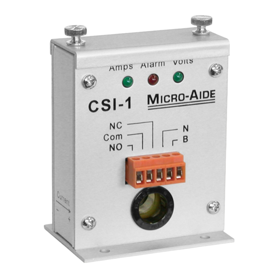
CSI-1
I
NDICATOR
U
M
SER
ANUAL
E-mail: support@micro-aide.com
Advertisement
Table of Contents

Summary of Contents for Micro-Aide CSI-1
- Page 1 CSI-1 HARGE TATUS NDICATOR ANUAL ICRO IGNAL RODUCTS VENT ECORDERS PEED ONITORS URRENT ENSORS SOLATED ODEMS ATTERY ONITORS OLTAGE ONITORS IGHT ETECTORS LOCK YNCHRONIZERS HISTLE ETECTORS OCAL ONTROL ANELS USTOM NGINEERING Tel: 626-915-5502 Fax: 626-331-9484 E-mail: support@micro-aide.com ICRO ORPORATION 685 Arrow Grand Circle Covina, CA 91722...
- Page 2 Four mounting holes at the base of the unit are charger fail to provide an adequate charging current used to secure the CSI-1. It is advisable to mount the under these conditions the CSI-1 will immediately unit in such a way that the front panel LEDs are indicate an alarm condition.
- Page 3 “Com” terminal when the CSI-1 Reinstall the cover plate after the voltage limit value is indicating a failure or power is removed. has been set. The CSI-1 is ready for use. The current carrying conductor from the charger to Reminder - The adjustable DVM voltage reading the battery is passed through the hole in the CSI-1.
- Page 4 Figure 1 - Three-sided view...
- Page 5 Inside View with Cover Removed Limit level equals 10 times DVM voltage reading Warning! Voltage adjust Do not adjust Pot (20 turn) Reference test Voltage adjust point (green) test point (red) Figure 2 - Inside view...
- Page 6 CSI-1 HARGE TATUS NDICATOR PECIFICATIONS Physical Spec Protection Controls Size Isolation Internal Length: 3.0" Minimum 4000 Vdc to ground, Potentiometer: 20-turn, used to infinite duration, to any terminal adjust voltage limit value Width: 2.125" input Test points: 2, female, used to Height: 4.1"...
Need help?
Do you have a question about the CSI-1 and is the answer not in the manual?
Questions and answers