Advertisement
Quick Links
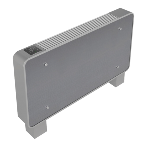
SERIES MINIFAN BASE
MANUALE DI INSTALLAZIONE E USO
INSTALLATION AND OPERATING MANUAL
EINBAU- UND BEDIENUNGSANLEITUNG
MANUEL D'INSTALLATION ET MODE D'EMPLOI
MANUAL DE INSTALACIÓN Y USO
ATTENZIONE Leggere questo manuale accuratamente prima di usare l'apparecchio ed eseguire le operazioni come
indicato. Le istruzioni sono importanti per la sicurezza e per un corretto funzionamento; accertarsi di osservarle.
WARNING Please read this manual carefully before using the equipment; carry well out all the operations here
indicated. The section explains how to use the equipment safety and correctly. Observe the precautions given in this
manual and on plates and tables attached to the unit.
ACHTUNG Bitte lesen Sie genau diese Anleitung vor Gebrauch des Geräts und die Verfahren auf korrekte Weise
durchführen. Die in diesem Abschnitt beschriebenen Anweisungen beziehen sich auf einen für die Sicherheit
korrekten Betrieb; diese Anweisungen unbedingt befolgen.
ATTENTION Avant d'utiliser l'appareil, lire attentivement ce manuel et effectuer les opérations de la juste façon.
Les instructions décrites dans cette section assurent un fonctionnement correct; s'assurer de bien les respecter.
ATENCION Es necesario leer cuidadosamente el presente manual antes de usar el equipo. La lectura de la guia
ayuda la ejecucion correcta de los procedimientos y garantizan un correcto funcionamiento de la unidad.
MIU.MINIFAN BASE.018.22
1
Advertisement

Summary of Contents for Dynergy MINIFAN BASE Series
- Page 1 SERIES MINIFAN BASE MANUALE DI INSTALLAZIONE E USO INSTALLATION AND OPERATING MANUAL EINBAU- UND BEDIENUNGSANLEITUNG MANUEL D’INSTALLATION ET MODE D’EMPLOI MANUAL DE INSTALACIÓN Y USO ATTENZIONE Leggere questo manuale accuratamente prima di usare l’apparecchio ed eseguire le operazioni come indicato. Le istruzioni sono importanti per la sicurezza e per un corretto funzionamento; accertarsi di osservarle. WARNING Please read this manual carefully before using the equipment;...
- Page 2 INDEX INDEX INDICE - - INHALTSVERZEICHNIS - - INDICE Premessa – Introduction – Einführung – Introduction -Introducción Identificazione unità - Identification of the unit - Kenndaten der Einheit - Identification de l'unité – Identificación de la unidad - Technical features Caractéristiques techniques Caratteristiche tecniche - Technische Merkmale -...
- Page 3 User Information Manual or any inspection, repair and maintenance requirement. This booklet must always accompany the appliance, being considered an integral part of such. MINIFAN BASE series is CE - LVD -EMC certified by SGS laboratories...
- Page 4 Wir gratulieren Ihnen zur Wahl eines Gebläsekonvektors MINIFAN BASE. Das vorliegende Handbuch enthält die für Transport, Installation, Bedienung und Wartung der Einheiten erforderlichen Informationen. Die Missachtung der Anleitungen bzw. eine unsachgemäße Installation der Geräte können zum Verfall der vom Hersteller geleisteten Garantie führen. Der Hersteller haftet nicht für eventuelle direkte bzw. indirekte Schäden infolge falscher Installationen bzw.
- Page 5 Congratulaciones por elegir un ventilconvector MINIFAN BASE. Este manual presenta todas las informaciones utiles para el transporte, instalacion, uso y manutencion de las unidades. De no seguirse las instrucciones aqui descritas y/o en caso de una inadecuada instalacion de las unidades, el fabricante se reserva el derecho de anular la garantia.
- Page 6 IDENTIFICATION OF THE UNIT IDENTIFICAZIONE UNITÀ - - KENNDATEN DER EINHEIT - IDENTIFICATION DE L'UNITE- IDENTIFICACIÓN DE LA UNIDAD Sur chaque unité MINIFAN Le unità MINIFAN BASE Seitlich von den Geräten MINIFAN BASE units BASE est apposée une Las unidades MINIFAN sono dotate di una der Einheit MINIFAN feature a dataplate...
- Page 7 MAIN COMPONENTS COMPONENTI PRINCIPALI - - HAUPTBESTANDTEILE – COMPOSANTES PRINCIPALES - COMPONENTES PRINCIPALES Parti esterne – External parts – Außenteileb - Parties externes - Außenteile Right-hand side flank Panneau latéral droit Fianco laterale destro Rechtes Seitenteil Panel lateral derecho Fianco laterale sinistro Left-hand side flank Linkes Seitenteil Panneau latéral gauche...
- Page 8 Parti interne – Internal parts – Interne Teile - Parties internes - Partes internas. Vertical unit Unità verticale – – Unité verticale Vertikale Einheit - - Unidad vertical. Fianco interno Internal flank innere Flanke flanc interne flanco interno Scambiatore principale Main heat-exchanger Hauptwärmetauscher Echangeur principal...
- Page 9 Parti interne – Internal parts – Interne Teile - Parties internes - Partes internas. Horizontal unit Unità orizzontale – Unité horizontale Horizontale Einheit - - Unidad horizontal. Fianco interno Internal flank innere Flanke flanc interne flanco interno Scambiatore principale Main heat-exchanger Hauptwärmetauscher Echangeur principal Batería principal...
- Page 10 DATI TECNICI-TECHNICAL DATA-TECHNISCHE DATEN-DONNÉES TECNIQUES–DATOS TÉCNICOS 2 pipe system Installation 2 tubes Impianto a 2 tubi – – 2 Leiter-System - – Instalación 2 tubos REFROIDISSEMENT RAFFRESCAMENTO COOLING MODE KÜHLBETRIEB ENFRIAMIENTO Ambiante:27 °C - 47 % HR Room:27° C – 47% R.H. T.ambiente:27 °C - 47 % UR , Raum: 27°C–...
- Page 11 2 pipe system Installation 2 tubes Impianto a 2 tubi – – 2 Leiter-System - – Instalación 2 tubos HEIZUNG HEATING MODE CHAUFFAGE RISCALDAMENTO CALEFACCIÓN Raumtemp.: 20°C T.ambiente:20 °C, Room:20° C. Temp. ambiante : 20 °C Temp. ambiente: 20°C Wassertemp.IN: 50°C Water temp.
- Page 12 4 pipe system Installation 4 tubes Impianto a 4 tubi – – 4 Leiter-System - – Instalación 4 tubos REFROIDISSEMENT RAFFRESCAMENTO COOLING MODE KÜHLBETRIEB ENFRIAMIENTO Ambiante:27 °C - 47 % HR Room:27° C – 47% R.H. T.ambiente:27 °C - 47 % UR , Raum: 27°C–...
- Page 13 4 pipe system Installation 4 tubes Impianto a 4 tubi – – 4 Leiter-System - – Instalación 4 tubos HEIZUNG HEATING MODE CHAUFFAGE RISCALDAMENTO CALEFACCIÓN Raumtemp.: 20°C T.ambiente:20 °C, Room:20° C. Temp. ambiante : 20 °C Temp. ambiente: 20°C Wassertemp.IN: 50°C Water temp.
- Page 14 Numero ranghi scambiatore principale Number of rows of main coil Reihenzahl Hauptregister Nombre de rangées de la batterie principale Número rangos batería principal Attacchi batteria – Coil connection Connexions de la batteri Batterieverbindungen - 1/2” GF 1/2” GF 1/2” GF 1/2”...
- Page 15 NOISE LEVEL DATA DONNEES BRUIT – DATI DI RUMOROSITA’ - - LÄRMBELASTUNG - NIVEL DE RUIDO Sound power Puissance Sound pressare Potenza sonora - - Schallleistung - Pressione sonora - acoustique Pression acoustique Potencia sonora Schalldruck - Presión sonora DC SERIES DC SERIES [dB(A)] [dB(A)]...
- Page 16 DIMENSIONS AND WEIGHTS – DIMENSIONI E PESI – ABMESSUNGEN UND GEWICHTE – DIMENSIONS ET POIDS - DIMENSIONES Y PESOS Vertical Models Modelli verticali – – Vertikale Modelle – Modèles verticaux - Modelos verticales VISTA FRONTALE FRONTAL VIEW SCARICO DRAIN 16mm FILTRO FILTER L’unità...
- Page 17 Horizontal Models Modelli orizzontali – – Horizontale Modelle – Modèles horizontaux - Modelos horizontales VISTA FRONTALE FRONTAL VIEW VISTA DESTRA RIGHT SIDE VIEW VISTA POSTERIORE REAR VIEW 1/2"GF SCARICO DRAIN filter Ø INDICA IL DIAMETRO DEL FORO PER IL PASSAGGIO DEL TUBO DI SCARICO SI CONSIGLIA DI USARE UN TUBO DIAMETRO ESTERNO 17MM E INTERNO 12MM Ø...
- Page 18 INSTALLATION INSTRUCTIONS 3. ISTRUZIONI PER L’INSTALLAZIONE - INSTRUCTIONS POUR L’INSTALLATION INSTALLATIONSANWEISUNGEN - INSTRUCCIONES PARA LA INSTALACIÓN WARNINGS AVERTISSEMENTS- AVVERTENZE - - WICHTIGE HINWEISE – ADVERTENCIAS Unità per installazione all'interno. Per la movimentazione delle unità utilizzare mezzi adeguati come previsto dalla direttiva 2007/30/CE e successive modifiche. La ditta costruttrice declina qualsiasi responsabilità...
- Page 19 Unitè pour installation à l'interieur. Pour la manutention des unités, utiliser des appareils ou engins de levage appropriés conformément aux dispositions de la directive 2007/30/CEE et modificatifs Le constructeur décline toute responsabilité en cas de non-respect des règles de sécurité et de prévention suivantes. La responsabilité...
- Page 20 POSITIONING OF THE UNIT POSIZIONAMENTO DELL’UNITÀ - - POSITIONIERUNG DER EINHEIT - EMPLACEMENT DE L'UNITE - POSICIONAMIENTO DE LA UNIDAD Posizionare l’unità su di una struttura idonea a sopportare il peso della macchina. Si consiglia di utilizzare sistemi antivibranti, tali da impedire la trasmissione delle vibrazioni alla struttura stessa.
- Page 21 RIMOZIONE DEL PANNELLO FRONTALE REMOVAL OF THE FRONTAL PANEL ENTFERNUNG DER FRONTSEITE RETRAIT DE LA FACE AVANT DESMONTAJE DEL PANEL FRONTAL Rimuovere il pannello frontale facendo attenzione a non danneggiarlo. Assicurarsi che sia depositato in un posto sicuro e protetto. Remove the front panel, taking care not to damage it.
- Page 22 Procedere alla rimozione del fianco destro e sinistro come indicato nell’immagine alla sinistra. Remove the right and left metal flanks as indicated in the image on the left. Entfernen Sie die rechten und linken Metallflanken wie in der Abbildung links gezeigt. Retirez les flancs métalliques droit et gauche comme indiqué...
- Page 23 PROCEDIMENTO PER AVERE LE CONNESSIONI IDRAULICHE SUL LATO SINISTRO (SOLO MODELLI VERTICALI). HOW TO PASS FROM RIGHT TO LEFT HYDRAULIC CONNECTIONS (ONLY VERTICAL MODEL). WIE SIE VON HYDRAULISCHER ANSCHLUSS VON RECHTS NACH LINKS GEHEN (NUR VERTIKALISCHES MODELL). COMMENT PASSER DE CONNEXION HYDRAULIQUE DE DROITE À GAUCHE (UNIQUEMENT MODÈLE VERTICAL). CÓMO PASAR DESDE EL DERECHO A LA IZQUIERDA CONEXIÓN HIDRÁULICA (SOLO MODELO VERTICAL).
- Page 24 Dopo avere rimosso il fianco in metallo sul lato della scheda elettronica come indicato nelle sezioni precedenti, rimuovere le due viti indicate nella prima immagine in alto e procedere a ruotare la scatola elettrica come indicato nell’immagine sucessiva. Alla fine, riposizionare le 2 viti. After metal flank removal (only electronic board side) as shown in the previous sections, remove the 2 screws indicated in the first picture on the top and...
- Page 25 ACCESSO ALLE PARTI INTERNE (VENTILATORE, SCAMBIATORE AD ACQUA E VASCHETTA RACCOLTA CONDENSA PRINCIPALE). ACCESS TO INTERNAL PARTS (FAN BLOWER, COIL AND MAIN DRAIN PAN). ZUGANG ZU INNENTEILEN (VENTILATOR, AUSTAUSCHER UND HAUPTABLAUFWANNE) ACCÈS AUX PARTIES INTERNES (VENTILATEUR, ÉCHANGEUR ET PANNEAU DE DRAIN PRINCIPAL). ACCESO A PIEZAS INTERNAS (SOPORTE DE VENTILADOR, INTERCAMBIADOR Y BANDEJA DE DESAGÜE PRINCIPAL).
- Page 26 RIPOSIZIONAMENTO DEL PANNELLO FRONTALE IN VETRO REPOSITIONING OF THE FRONTAL GLASS PANEL NEUPOSITIONIERUNG DER VORDEREN GLASPLATTE REPOSITIONNEMENT DU PANNEAU DE VERRE AVANT REPOSICIONAMIENTO DEL PANEL FRONTAL DE VIDRIO Riposizionare il pannello sull’unità Reposition the panel on the unit Positionieren Sie die Blende wieder am Gerät Repositionner le panneau sur l'unité...
- Page 27 FIXING THE UNIT FISSAGGIO DELL’UNITÀ - FIXATION DE L'UNITE BEFESTIGUNG DER EINHEIT - - FIJACIÓN DE LA UNIDAD B (mm) Predisporre le forature secondo le quote della figura sopra. Fissare quattro tiranti filettati M6. Nota: assieme all’unità viene fornita una dima in scala 1:1. Usare la dima per posizionare l’unità. Drill the fixing holes in accordance with dimensions shown in the above figure.
- Page 29 HYDRAULIC CONNECTIONS COLLEGAMENTI IDRAULICI - -WASSERANSCHLÜSSE – CONNECTIONS HYDRAULIQUES - CONEXIONES HIDRÁULICAS Gli scambiatori delle unità sono forniti di attacchi filettati gas “femmina” (1/2” GF). La pressione massima di esercizio delle batterie non deve superare i 6 bar Rispettare le indicazioni poste sul fianco delle unità relative all’entrata e all’uscita dell’acqua nella batteria. Durante l’allacciamento degli apparecchi senza valvole serrare i tubi con cautela per evitare possibili danneggiamenti.
- Page 30 Hydraulic connections pipe Tubazioni per collegamento – – Hydraulikanschlussleitung – Tuyau de raccordement hydraulique - Tubería de conexiones hidráulicas. Φ acciaio (”) Φ rame (mm) Φ multistrato (mm) Φ Steel (”) Φ copper (mm) Φ multilayer pipe (mm) MINIFAN BASE Φ...
- Page 31 ELECTRICAL CONNECTIONS COLLEGAMENTI ELETTRICI - - ELEKTRISCHE ANSCHLÜSSE - RACCORDEMENTS ÉLECTRIQUES - CONEXIONES ELÉCTRICAS Prima di iniziare qualsiasi operazione assicurarsi che la linea di alimentazione generale sia sezionata. Before starting any work on the appliance make sure the main electrical power supply line has been disconnected. Bevor Sie mit irgendeiner Operation beginnen, müssen Sie sicherstellen, dass die allgemeine Stromzuleitung unterbrochen ist.
- Page 32 WIRING DIAGRAMS SCHÉMAS ÉLECTRIQUES - 4. SCHEMI ELETTRICI - - SCHALTBILDER - DIAGRAMAS ELÉCTRICOS Ci sono due modi per controllare le unità: Termostato remoto da posizionare a muro, in un adeguato posto e ad un’altezza di circa 1,5m dal pavimento. Termostato a bordo unità.
- Page 33 CLOSE HEAT VALVE OPEN CLOSE COOL VALVE OPEN HIGH AC220V-N AC220V-L PUMP HEATER FILTER HEATING COOLING 230V-50 Hz STEP1 COM1 ROOM WATER...
- Page 34 HEATER FILTER PUMP HEATING COOLING STEP1 COM1 ROOM WATER...
- Page 35 CLOSE HEAT VALVE OPEN CLOSE COOL VALVE OPEN HIGH AC220V-N AC220V-L HEATER FILTER PUMP HEATING COOLING 230V-50 Hz STEP1 COM1 ROOM WATER...
- Page 36 CLOSE HEAT VALVE OPEN CLOSE COOL VALVE OPEN HIGH AC220V-N AC220V-L HEATER FILTER PUMP HEATING COOLING 230V-50 Hz STEP1 COM1 ROOM WATER...
- Page 37 HEATER FILTER PUMP HEATING COOLING STEP1 COM1 ROOM WATER...
- Page 38 CLOSE VALVOLA RISCALD. OPEN CLOSE VALVOLA CONDIZION. OPEN HIGH AC220V-N AC220V-L HEATER FILTER PUMP HEATING COOLING 230V-50 Hz STEP1 COM1 ROOM WATER...
- Page 39 Dip switch setting for RPM Réglage du Settaggi dip switch per giri motore – - DIP-Schalter für RPM - commutateur DIP pour RPM - Ajuste del interruptor DIP para RPM...
- Page 40 MAINTENANCE AND CHECKS 5. MANUTENZIONI E CONTROLLI – - WARTUNG UND ENTRETIEN ET CONTRÔLES KONTROLLEN - – MANUTENCIÓN Y CONTROLES Verificare periodicamente che la batteria di scambio termico sia pulita. Verificare il serraggio di viti, bulloni, connessioni idriche ed elettriche, che potrebbero essersi allentate in conseguenza delle vibrazioni indotte dal funzionamento della macchina.
- Page 41 FAULT FINDING - PROBLEMBEHANDLUNGSVERFAHREN - 6. PROCEDURA GUASTI – DEPANNAGE – BÚSQUEDA DE AVERÍAS Fare eseguire i controlli necessari solo a personale qualificato Ensure that the various checks and inspections are performed exclusively by appropriately qualified personnel Lassen Sie die erforderlichen Kontrollen nur durch Fachpersonal durchführen. Toutes ces opérations de contrôle doivent être effectuées uniquement par un professionnel qualifié.
- Page 42 ACCESSORIES INSTRUCTIONS 7. ISTRUZIONI INSTALLAZIONE ACCESSORI / / ANLEITUNG INSTRUCTIONS ACCESSOIRES ZUM ZUBEHÖR / / INSTRUCCIONES DE ACCESORIOS H2OPR La sonda acqua viene usata come termostato di minima e di massima e va posizionata dall’installatore sul pozzetto dello scambiatore, a ridosso di un tubo il più possibile vicino all’ingresso della batteria. La sonda deve misurare la temperatura dell’acqua fornita dall’unità...
- Page 43 E’ possibile usare una sonda NTC come accessorio da posizionare nel pacco allettato della batteria, in corrispondenza dell’ingresso della stessa batteria con funzione di termostato di minima e di massima. In questo modo, in riscaldamento il ventilatore partirà solo se la temperatura dell’acqua salirà sopra i 35°C e si fermerà quando la temperatura dell’acqua scenderà...
- Page 44 NOTE FOR ALL THE VALVES NOTA PER L’INSTALLAZIONE DELLE VALVOLE. INSTALLATION NOTE POUR TOUTE . HINWEIS FÜR ALLE VENTILINSTALLATIONEN. L'INSTALLATION DES VANNES. NOTA PARA TODAS LAS INSTALACIONES DE VÁLVULAS. Si consiglia di rimuovere il pannello frontale frontale in corrispondenza del ventilatore e di far passare i cavi dell’attuatore/i come nella foto a sinistra It is recommended to remove the front front panel at the fan and to pass the cables of the actuator / s as in...
- Page 45 FLOW RATE/PRESSURE DROP CHARTS GRAFICI PORTATA/PERDITA DI CARICO. DIAGRAMMES DE DÉBIT/PERTE DE CHARGE. DURCHFLUSS-/DRUCKVERLUSTDIAGRAMME. GRÁFICOS DE CAUDAL / CAÍDA DE PRESIÓN.
- Page 49 V22RFSAMK8 – 2 WAY VALVE WITH MICRO BASE 80...
- Page 52 V23RFSAMK8 – 3 WAY VALVE WITH MICRO FOR 80 V22RFSAMK 2/6 - V22RFSAMK 8 - V23RFSAMK 2/6 - V23RFSAMK 8 VALVE WITH MICRO VERSION - VANNE AVEC MICRO VALVOLA CON MICRO - VENTIL MIT MIKRO – - VÁLVULA CON MICRO filo marrone - brown wire - braunes kabel - fil marron - alambre marrón...
- Page 54 Isolare tutti i tubi ed entrambe le valvole, poiché non viene utilizzata alcuna vaschetta di raccolta ausiliaria. Insulate all the pipes and both the valves, because no auxiliary drain pan is used. Isolieren Sie alle Rohre und beide Ventile, da keine zusätzliche Ablaufwanne verwendet wird. Isolez tous les tuyaux et les deux vannes, car aucun bac de récupération auxiliaire n'est utilisé.
- Page 55 GIV23-2/6 INSULATION SHELLS KIT FOR 3 WAY VALVE FOR HORIZONTAL MINIFAN BASE VERSION SIZE 20, 40, 60 NUMBE DESCRIPTION QUANTIT ½ “3-WAY VALVE INSULATING SHELL 2a-2b INSULATING SHELL FOR LONG PIPE 3a-3b INSULATING SHELL FOR SHORT PIPE FLEX INSULATING SHELL CLOSURE Installare la valvola nell’unità...
- Page 56 Posizionare i gusci (3a) e (2b) sui tubi come nell’immagine a fianco. Position the shells (3a) and (2b) on the pipes as in the image alongside. Positionieren Sie die Schalen (3a) und (2b) auf den Rohren wie im nebenstehenden Bild. Positionnez les coques (3a) et (2b) sur les tuyaux comme sur l'image ci-contre.
- Page 57 Coloque la carcasa (3b) de modo que cubra todo el tubo y encaje en la carcasa (3a). Chiudere i gusci con le apposite graffette (4) in tre punti per ogni tubo, assicurandosi che siano saldamente posizionate. Close the shells with the appropriate clips (4) in three places for each tube, making sure they are firmly in place.
- Page 58 Posizionare il guscio (1) attorno al corpo valvola e chiuderlo nella parte superiore con due graffette (4). Place the shell (1) around the valve body and close it at the top with two clips (4). Die Schale (1) um den Ventilkörper legen und oben mit zwei Clips (4) verschließen.
- Page 59 GIV23-8 INSULATION SHELLS KIT FOR 3 WAY VALVE FOR HORIZONTAL MINIFAN BASE VERSION SIZE 80 NUMBE DESCRIPTION QUANTIT 3/4 "3-WAY VALVE INSULATING SHELL 2a-2b INSULATING SHELL FOR LONG PIPE 3a-3b INSULATING SHELL FOR SHORT PIPE FLEX INSULATING SHELL CLOSURE Installare la valvola nell’unità (fare riferimento alle rispettive istruzioni).
- Page 60 Posizionare i gusci (3b) e (2b) sui tubi come nell’immagine a fianco. Position the shells (3b) and (2b) on the pipes as in the image alongside. Positionieren Sie die Schalen (3b) und (2b) auf den Rohren wie im nebenstehenden Bild. Positionnez les coques (3b) et (2b) sur les tuyaux comme sur l'image ci-contre.
- Page 61 Chiudere i gusci con le apposite graffette (4) in tre punti per ogni tubo, assicurandosi che siano saldamente posizionate. Close the shells with the appropriate clips (4) in three places for each tube, making sure they are firmly in place. Verschließen Sie die Schalen mit den entsprechenden Clips an drei Stellen für jedes Rohr und stellen Sie sicher, dass sie...
- Page 62 Una volta completati i passaggi precedenti, assicurarsi che non siano presenti parti scoperte che potrebbero provocare la formazione di condensa e il gocciolamento. Once you have completed the above steps, make sure there are no exposed parts that could cause condensation and dripping.
- Page 63 WALL PAD METAL SUPPORT 1 NUMBER DESCRIPTION WALL PAD METAL SUPPORT 1 METAL SUPPORT 2 SCREW M4*10FH ADJUST POSITION ON TOP OF WALL PAD...
- Page 64 This picture is relative to the discharging pipe placing and positioning.! Use install map fix screw on ground Fix machine with screw DESCRIPTION NUMB Left feet Right feet Left cover Right cover screw...
- Page 65 Check always the body fix well.
- Page 66 FKR FEET MINIFAN BASE 20/80 RPEHFS 20-40 RADIANT PANEL heater Paste the heating film on the glass panel Connect heater to PCB DESCRIPTION NUMBER Flexible heater MINIFAN BASE 20-40...
- Page 67 Check connected well.
- Page 68 RPEHFS 60-80 RADIANT PANEL heater Connect heater to PCB Paste the heating film on the glass panel DESCRIPTION NUMBER Flexible heater MINIFAN BASE 60-80 Check connected well.
- Page 69 BAPRFS Back Aesthetic Panel Posizionare il pannello sullo schienale dell’unità. Position the panel in the back side of the unit. Positionieren Sie das Bedienfeld auf der Rückseite des Geräts. Positionnez le panneau à l'arrière de l'unité. Coloque el panel en la parte posterior de la unidad.
- Page 70 DIBOND AESTHETIC FRONTAL PANEL Rimuovere le viti dal pannello in vetro (se gia posizionato). Remove the screws from the glass panel (if already in place). Entfernen Sie die Schrauben von der Glasscheibe (falls bereits vorhanden). Retirez les vis du panneau de verre (si déjà en place). Quite los tornillos del panel de vidrio (si ya está...
- Page 71 Limpiar el panel con un paño de microfibra húmedo, no utilizar productos agresivos y prestar mucha atención a los paneles impresos.
- Page 72 HCTFS Horizontal collector tray Posizionare l’unità su un tavolo, rimuovere il pannello frontale in vetro, i pannelli interni isolati e la vaschetta raccolta condensa. Position the unit on a table, remove the glass frontal panel, then proceed with internal insulated panels and main drain pan removal.
- Page 73 Tous les tuyaux et les vannes doivent être isolés par l'installateur, car aucun bac de vidange auxiliaire n'est utilisé. L'utilisation de coques isolantes est recommandée. L'unité doit être installée avec une pente d'un degré. Utilisez le trou indiqué à gauche pour le tuyau de décharge Vérifiez la décharge correcte de la condensation.
- Page 74 Template Modèles Dime di riscontro / / Vorlagen / / Plantillas. MINIFAN BASE 20 Distanza minima - Minimum distance 200mm - Back machine shape Distanza minima - Asole di fissaggio al muro Minimum - Use metal anchor to fix machine to the wall distance 10mm Connessioni idrauliche dal muro Plumbing connection from wall...
- Page 75 MINIFAN BASE 40 Distanza minima - Minimum distance 200mm - Back machine shape Distanza - Asole di fissaggio al muro minima Minimum - Use metal anchor to fix machine to the wall distance 10mm Distanza Connessioni idrauliche dal muro minima Plumbing connection from wall Minimum Connessioni elettriche dal muro...
- Page 76 MINIFAN BASE 60 70 55 1065 45 45 8 12 Ø10...
- Page 77 MINIFAN BASE 80 70 55 1257 45 45 8 12 Ø10 22 69...
- Page 78 GENERAL WIRING DIAGRAMS. SCHEMI ELETTRICI FUNZIONALI. ALLGEMEINE SCHÉMAS GÉNÉRAUX DE CÂBLAGE. SCHALTPLÄNE. DIAGRAMAS DE CONEXIONES GENERALES. CLOSE HEAT VALVE OPEN CLOSE COOL VALVE OPEN HIGH AC220V-N AC220V-L HEATER FILTER PUMP HEATING COOLING 230V-50 Hz STEP1 COM1 ROOM WATER...
- Page 79 HEATER FILTER PUMP HEATING COOLING STEP1 COM1 ROOM WATER...
- Page 80 CLOSE HEAT VALVE OPEN CLOSE COOL VALVE OPEN HIGH AC220V-N AC220V-L HEATER FILTER PUMP HEATING COOLING 230V-50 Hz STEP1 COM1 ROOM WATER...
- Page 82 CLOSE HEAT VALVE OPEN CLOSE COOL VALVE OPEN HIGH AC220V-N AC220V-L HEATER FILTER PUMP HEATING COOLING 230V-50 Hz STEP1 COM1 ROOM WATER...
- Page 83 HEATER FILTER PUMP HEATING COOLING STEP1 COM1 ROOM WATER...
- Page 84 CLOSE HEAT VALVE OPEN CLOSE COOL VALVE OPEN HIGH AC220V-N AC220V-L HEATER FILTER PUMP HEATING COOLING 230V-50 Hz STEP1 COM1 ROOM WATER...
- Page 86 CLOSE HEAT VALVE OPEN CLOSE COOL VALVE OPEN HIGH AC220V-N AC220V-L HEATER FILTER PUMP HEATING COOLING 230V-50 Hz STEP1 COM1 ROOM WATER...
- Page 87 CLOSE HEAT VALVE OPEN CLOSE COOL VALVE OPEN HIGH AC220V-N AC220V-L HEATER FILTER PUMP HEATING COOLING 230V-50 Hz STEP1 COM1 ROOM WATER...
- Page 88 GENERIC HYDRAULIC DIAGRAM SCHEMA IDRAULICO GENERICO ALLGEMEINES SCHÉMA HYDRAULIQUE GÉNÉRIQUE HYDRAULIKDIAGRAMM ESQUEMA HIDRÁULICO GENÉRICO...
Need help?
Do you have a question about the MINIFAN BASE Series and is the answer not in the manual?
Questions and answers