Table of Contents
Advertisement
Available languages
Available languages
Quick Links
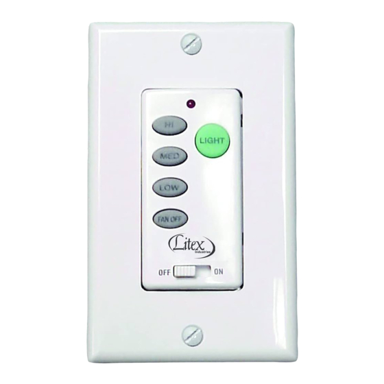
There are four buttons (Hi, Med, Low, Fan Off) to control the fan speed and one button (Light) to control the light.
The ON/OFF switch is to turn the power to wall control On or Off. The red indicator on the transmitter will light when any button is pressed.
I. SAFETY PRECAUTIONS
A.
DANGER: HIGH VOLTAGE! Household electrical power can cause serious injury or death. Disconnect source of electrical power to the ceiling
fan by removing fuse or switching off circuit breaker. Make sure all electrical connections comply with local codes, ordinances, the National Electrical Code,
and ANSI/NFPA 70-1999. If you are unfamiliar with electrical wiring, please use a qualified and licensed electrician.
B.
WARNING: To reduce the risk of fire, electrical shock, or personal injury, wire connectors provided with the remote control
receiver are designed to accept only one 12 gauge house wire and no more than two lead wires from the receiver. If your
house wire is larger than 12 gauge or there is more than one house wire to connect to the two receiver wires, consult an
electrician for the proper size wire connectors to use.
CAUTION:
C.
TO REDUCE THE RISK OF FIRE OR ELECTRIC SHOCK, DO NOT USE THE FAN
WITH ANY SOLID STATE SPEED CONTROL DEVICE OR CONTROL FAN SPEED WITH A FULL
RANGE DIMMER SWITCH.
D. Do not use this wall control with solid state ceiling fans.
Electrical source and fan must be 115/120 volts, 60 Hz.
Maximum fan motor amps: 1.0; Maximum light watts: 300 incandescent only.
II. INSTALLATION OF RECEIVER (Please refer to Figure 1 before continuing.)
Manually set fan speed control to HIGH via pull chain and set light to ON via pull chain.
A.
IMPORTANT:
Fan speed and light control will not be activated by wall control if pull chains
for fan and light are not set to the HIGH and ON positions, respectively.
B. Disconnect source of electrical power to the ceiling fan by removing fuse or switching off
circuit breaker.
C. Lower ceiling fan canopy from the mounting bracket.
D. Disconnect existing wiring between ceiling fan and supply at electrical outlet box.
E. Lay the black antenna wire on top of the receiver and slide the receiver into the
mounting bracket. (Figure 1)
F. Using the wire connectors supplied, make wiring connections as follows: (Figure 2)
CONNECT:
GREEN fan wire.....................................................BARE supply wire
BLACK receiver wire (AC IN L)..............................BLACK supply wire
WHITE receiver wire (AC IN N)..............................WHITE supply wire
WHITE receiver wire (TO MOTOR N).....................WHITE fan wire
BLACK receiver wire (TO MOTOR L).....................BLACK fan wire
BLUE receiver wire (FOR LIGHT)...........................BLUE light wire (from fan)
Wrap each wire connector separately with electrical tape as an extra safety measure.
If other fan or supply wires are different colors than those mentioned,
have this unit installed by a qualified electrician.
G. Push all connected wires up into outlet box. Make sure antenna rests outside of mounting bracket.
H. Re-install the canopy on the mounting bracket.
III. SETTING CODE ON WALL CONTROL (TRANSMITTER)
This unit has 16 different code combinations. To set the code perform these steps:
A. Setting the code on the wall control
Slide code switches 1 through 4 to your choice of up or down position. (Factory setting is all up).
Do not use this position. Use a small screwdriver or ballpoint pen to slide firmly up or down. (Figure 4)
B. Setting the dimmer switch
Locate the dimmer switch to the right of the code switches labeled with a "D" and an "X". Set dimmer switch to ON (D) position
only if using incandescent bulbs. Set dimmer switch to OFF (X) position if using compact fluorescent bulbs.
NOTE: Compact fluorescent bulbs are NOT compatible for use with dimmer controls.
IV. INSTALLING WALL CONTROL
Remove wall plate, disconnect and remove the toggle switch from wall outlet box. Using the wire connectors provided, make the electrical connections to the
wall control as shown in Figure 2. Wrap each wire connector separately with electrical tape as an extra safety measure.Carefully push all connected wires
back inside wall outlet box. Secure wall control with 2 screws provided. Attach wall plate cover with the 2 original screws.
V. AUTOMATED LEARNING PROCESS/ACTIVATING CODE
Restore electrical power. Within 30 seconds of restoring electrical power, press the "FAN OFF" button, located on the wall control, for 3 seconds or until light
on fan blinks twice. Test the light and fan functions to confirm the learning process is complete. (Figure 4) CAUTION: The wall control can be programmed to
multiple receivers or fans. If this is not desired, turn power off to any other programmable receiver or fan.
VI. WALL CONTROL--CARE AND OPERATION
A. This wall control unit is equipped with 16 code combinations to prevent possible interference from or to other
remote units such as garage door openers, car alarms or security systems. If you find that your fan and light kit
go on and off without using your wall control, simply change the combination code in your wall control. If you do
change the combination code turn power off and repeat Section V (Automated Learning Process) above.
B. Operation buttons on the front panel of the wall control:
HI button
for fan high speed
MED button
for fan medium speed
LOW button
for fan low speed
FAN OFF button
for fan speed off
LIGHT button
for light brightness and off
The light function is controlled by pressing the LIGHT button. Hold button down to increase or
decrease light. Tap button quickly to turn light off or on. If you press the button in excess of
0.7 second it becomes a dimmer. The light varies cyclically in 0.8 seconds. The light button
has auto resume, so the light will stay at the same brightness as the last time it was turned off.
IMPORTANT:
Make sure that fan has been turned off at wall switch and then allow
blades to come to a complete stop before manually activating the reverse switch on the fan.
VII. TROUBLESHOOTING GUIDE
A. Fails to operate:
1.
Power to the receiver?
2.
Receiver wired correctly?
3.
Manual speed control on fan in highest position?
4.
Light kit switch turned on?
5.
Learning process between fan and wall control may not have been successful.
Turn power off and repeat Section V (Automated Learning Process) above.
6.
Make sure the black antenna wire rests outside of hanging bracket.
GENERAL INFORMATION
This wall control is designed to separately control your ceiling fan speed and light brightness.
INSTALLATION AND OPERATING INSTRUCTIONS
TO:
20˚
above
19˚
CAUTION: FOR MOUNTING RECEIVER,
CEILING ANGLE SHALL NOT EXCEED
19 DEGREES; RECEIVER MODEL: UC7067RYA
AC SUPPLY
BLACK
WHITE
BLACK
GREEN
BLACK
BLACK
BLACK
WALL CONTROL
RECEIVER
WALL CONTROL
CAUTION:
TO REDUCE THE RISK OF FIRE OR ELECTRIC SHOCK, DO NOT
USE THE FAN WITH ANY SOLID STATE SPEED CONTROL DEVICE
OR CONTROL FAN SPEED WITH A FULL RANGE DIMMER SWITCH.
FOR CUSTOMER SERVICE CALL: 1-800-527-1292
MODEL: WCI-100L
MOUNTING
BRACKET
and
RECEIVER
DOWNROD
Fig. 1
ANTENNA
RECEIVER
BLUE
BLUE
BLACK
BLACK
WHITE
WHITE
BARE
GREEN
CANOPY
Fig. 2
CAUTION: DO NOT USE
FAN SPEED CONTROL
IN CANOPIES WHERE
THE MOUNTING IS NOT
AS SHOWN IN FIGURE 3
OF THE INSTALLATION
INSTRUCTIONS
Fig. 3
CODE
SWITCHES
DIMMER
SWITCH
WALL CONTROL
Fig. 4
FRONT PANEL
LITEX INDUSTRIES, LTD.
GRAND PRAIRIE, TX 75050
Advertisement
Table of Contents

Related Manuals for Litex Industries WCI-100L

Summary of Contents for Litex Industries WCI-100L
- Page 1 GENERAL INFORMATION MODEL: WCI-100L This wall control is designed to separately control your ceiling fan speed and light brightness. There are four buttons (Hi, Med, Low, Fan Off) to control the fan speed and one button (Light) to control the light.
- Page 2 MODELO: WCI-100L INFORMACION GENERAL Este control de pared está diseñado para controlar separadamente la velocidad de su ventilador de techo y la brillantez de la luz. Hay cuatro botones (alta, media, baja y apagado) para controlar la velocidad del ventilador y un botón para controlará la brillantez de la luz. El interruptor de apagado/encendido sirve para conectar o cortar la electricidad que va al control de pared.
Need help?
Do you have a question about the WCI-100L and is the answer not in the manual?
Questions and answers