Table of Contents
Advertisement
Quick Links
PG-F
LEX
Model
FRE-765
FRE-765
E
NGINEERING
R
T
EMOTE
List Number
P
G
T
AIR
AIN
ECHNOLOGIES
S
ERVICES
S
363-765-105-01
ECTION
Revision History of this practice.
Revision 01—June 2, 1997
A) Identifies List 5 x RT Enclosures
E
ERMINAL
Part Number
5
150-1365-05
5A
150-1365-51
, I
.
NC
T
P
ECHNICAL
RACTICE
NCLOSURE
Advertisement
Table of Contents

Related Manuals for CopperOptics PairGain PG-Flex FRE-765 List 5

Summary of Contents for CopperOptics PairGain PG-Flex FRE-765 List 5
- Page 1 PG-F EMOTE ERMINAL NCLOSURE Model List Number Part Number FRE-765 150-1365-05 FRE-765 150-1365-51 ECHNOLOGIES NGINEERING ERVICES ECHNICAL RACTICE 363-765-105-01 ECTION Revision History of this practice. Revision 01—June 2, 1997 A) Identifies List 5 x RT Enclosures...
-
Page 2: Table Of Contents
Section 363-765-105 June 2, 1997 Revision 01 TABLE OF CONTENTS A. PRODUCT OVERVIEW ........................1 1. Description and Features....................1 2. Specifications ........................3 B. FUNCTIONAL DESCRIPTION.....................3 3. Operational Capabilities ..................... 3 4. Backplane Connections...................... 5 C. INSTALLATION AND TEST......................10 5. Unpacking ........................10 6. -
Page 3: Product Overview
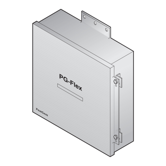
Revision 01 June 2, 1997 Section 363-765-105 A. PRODUCT OVERVIEW 1. Description and Features The PairGain® PG-Flex™ FRE-765 List 5x RemoteTerminal (RT) Enclosures (Figures 1 and 2) provide convenient mounting of one Line Unit and up to four Channel Units, supporting up to 32 channels. - Page 4 Section 363-765-105 June 2, 1997 Revision 01 Figure 2. FRE-765 List 5A RT Enclosure (Inside View) Features of the FRE-765 RT Enclosure List 5x include: • pole or wall mounting • line power from Central Office Terminal (COT) • AMP Quiet Front terminations for HDSL inputs, metallic bypass pair, and subscriber connections (List 5A only) •...
-
Page 5: Specifications
Revision 01 June 2, 1997 Section 363-765-105 Table 1. Features of FRE-765 5x RT Enclosures List 5 List 5A (Figure 1) (Figure 2) System 16 Channel 32 Channel Subscriber Terminations 25-pr Amphenol (male) AMP Insulation Displacement Subscriber Protection 5 pin sockets (short housing) HDSL Terminations AMP Insulation Displacement 2. - Page 6 Section 363-765-105 June 2, 1997 Revision 01 Table 2 shows how circuit assignments are configured in the FRE-765 with the following deployment rules: • For channel units providing four (4) circuits, Ckt 1 through Ckt 4 are used for Tip and Ring terminations.
-
Page 7: Backplane Connections
Revision 01 June 2, 1997 Section 363-765-105 4. Backplane Connections Table 4 lists the FRE-765 List 5x backplane connectors and where each connector is described in this practice. Table 4. FRE-765 List 5x Backplane Connectors List Connector or Fuse Go to Table(s) Page(s) Subscriber Connectors (16/32) - Page 8 Section 363-765-105 June 2, 1997 Revision 01 Table 6. List 5 Subscriber Cable J2 on Connector P2 (16/32 channels) Cable J2 Connector P2 Channel Unit Circuit Ring Ring WH/BL BL/WH WH/OR OR/WH WH/GN GN/WH WH/BN BN/WH WH/SL SL/WH RD/BL BL/RD RD/OR OR/RD RD/GN...
- Page 9 Revision 01 June 2, 1997 Section 363-765-105 Table 7. List 5A Subscriber Terminations Channel Subscriber Protector Unit Circuit Connector Pair Strip Socket (continued on next page) PG-Flex FRE-765 PairGain Engineering - Plant Series Page 7...
- Page 10 Section 363-765-105 June 2, 1997 Revision 01 Table 7. List 5A Subscriber Terminations (continued) Subscriber Protector Channel Unit Circuit Connector Pair Strip Socket For the FRE-765, List 5A RT Enclosure the cables on the rear of the protector/termination module are installed in connectors P3 and P2 on the FRE-765 backplane. Shaded terminations only used with the 8 Channel POTS or 4 Channel DDS Units.
- Page 11 Revision 01 June 2, 1997 Section 363-765-105 Table 9. HDSL, Metallic Bypass, and Auxiliary Power Line Unit Termination Backplane 6 Pair Cable Type Function Connector Stub (Lists 4D, 4E) HDSL_1_T WH/BL AMP Quiet Tip and Ring terminations for HDSL Pair #1 from the COT. -130 Vdc HDSL_1_R BL/WH Front...
-
Page 12: Installation And Test
Section 363-765-105 June 2, 1997 Revision 01 C. INSTALLATION AND TEST 5. Unpacking Upon receipt of the equipment: Unpack each container and visually inspect it for signs of damage. If the equipment has been damaged in transit, immediately report the extent of damage to the transportation company and to PairGain. -
Page 13: Mounting
Revision 01 June 2, 1997 Section 363-765-105 7. Mounting The FRE-765 mounts on a pole or a wall. Follow local practices to ensure a secure mounting. Mount the FRE-765 for easy access to the cable entry points on the bottom of the enclosure. Provide ample room to open the door completely. -
Page 14: Wiring
Section 363-765-105 June 2, 1997 Revision 01 Table 13 shows the wire gauges that can be installed through the holes in the grommet. Table 13. Grommet Hole Diameters For this grommet hole size Use this cable • .410 to .765 in. diameter (two) * 24 or 26 AWG, 25- or 50-pair Primary Interexchange Carrier (PIC) (filled or non-filled) •... - Page 15 Revision 01 June 2, 1997 Section 363-765-105 HDSL Lines. Install the HDSL lines (Figure 5): Route the HDSL pairs through the strain relief on the bottom of the enclosure. Terminate HDSL Pair #1 on the Quiet-Front terminals HDSL_1_T (Tip) and HDSL_1_R (Ring).
- Page 16 Section 363-765-105 June 2, 1997 Revision 01 Protector Plugs. For the FRE-765 List 5A, install five-pin protector plugs into the protector strips for each subscriber line installed (Figure 6). See Table 7 for protector socket locations. Figure 6. Installing Five-Pin Protector Plugs Auxiliary Power Pairs.
-
Page 17: Turn-Up And Testing
Revision 01 June 2, 1997 Section 363-765-105 Figure 7. Installing Doubler Termination Points Cabling Verification. Verify the following connections. Perform the following verifications before inserting any cards in the COT shelf. Visually ensure the ground wire is tightly secured to the grounding lug inside the FRE-765 and at the ground termination point. -
Page 18: Technical Support
Section 363-765-105 June 2, 1997 Revision 01 D. TECHNICAL SUPPORT 11. Technical Support 11.1 PairGain Technical Assistance is available 24-hours-a-day, 7-days-a-week by contacting PairGain Customer Service Engineering group at: Telephone: (800) 638-0031 or (714) 832-9922 Fax: (714) 832-9924 11.2 During normal business hours (8:00 AM to 5:00 PM, Pacific Time, Monday - Friday, excluding holidays), technical assistance calls are normally answered directly by a Customer Service Engineer. -
Page 19: Certification
Revision 01 June 2, 1997 Section 363-765-105 13. Certification 13.1 FCC Compliance. The FRE-765 List 5x RT Enclosure has been tested and found to comply with the limits for Class A digital devices pursuant to Part 15 of the FCC rules. These limits are designed to provide reasonable protection against harmful interference when the equipment is operated in a commercial environment.
Need help?
Do you have a question about the PairGain PG-Flex FRE-765 List 5 and is the answer not in the manual?
Questions and answers