
Related Manuals for CopperOptics PairGain PG-FlexPlus PCS-719


Summary of Contents for CopperOptics PairGain PG-FlexPlus PCS-719
- Page 1 PG-F ECHNICAL RACTICE 23-inch Central Office Terminal Shelf Model Number List Number CLEI Code PCS-719 S9MTCB0A~~ Section SCP-PCS719-011-01H...
- Page 2 SCP-PCS719-011-01H, Revision History of This Practice Revision Release Date Revisions Made July 10, 2001 Initial Release ©Copyright 2001 ADC DSL Systems, Inc. All Rights Reserved. Plus PairGain and PG-Plus are registered trademarks, and PG-Flex is a trademark of PairGain Technologies, Inc. ADC is a registered trademark of ADC Technologies, Inc.
- Page 3 SCP-PCS719-011-01H Using This Technical Practice SING ECHNICAL RACTICE Two types of messages, identified by icons, appear in the text. Notes indicate information about special circumstances. Cautions indicate the possibility of equipment damage or the possibility of personal injury. NSPECTING HIPMENT Upon receipt of the equipment: •...
-
Page 4: Table Of Contents
Table of Contents SCP-PCS719-011-01H ABLE OF ONTENTS Overview ____________________________________________________________________________ 1 Description and Features ........................1 Composite Clock Signals ........................2 Backplane Connections ........................2 Power ..........................3 HDSL ..........................3 Two-Wire Subscriber Circuits .................... 3 Four-Wire Subscriber Circuits .................... 3 COLU Edge Card Connectors..................... - Page 5 SCP-PCS719-011-01H Table of Contents Subscriber Connections From CO ..................30 Composite Clock Connections ..................37 DSX-1 Connections ......................38 HDSL Wiring ........................39 Test Connection .........................41 External ACO Connection....................42 Turn-Up and Test ..........................42 Abbreviations _______________________________________________________________________ 43 Product Support _____________________________________________________________________ 44 Technical Support ..........................44 World Wide Web ..........................44 Limited Warranty ..........................44 Returns .............................45 FCC Class A Compliance ........................46...
- Page 6 List of Tables SCP-PCS719-011-01H, IST OF ABLES 1. PCS-719 Backplane Connectors ........................3 2. COLU #1 (J4) Connector Pinouts ........................4 3. COLU #2 (J5) Connector Pinouts ........................4 4. COLU #3 (J6) Connector Pinouts ........................5 5. COLU #4 (J7) Connector Pinouts ........................5 6.
- Page 7 SCP-PCS719-011-01H List of Figures IST OF IGURES 1. Front View of the PCS-719 COT Shelf......................1 2. PCS-719 Shelf Backplane ..........................2 3. Alarm Relay Contacts from PAU/PMU to COT Shelf Backplane Wire-Wrap Field ........12 4. Modem Connection for PCS-719 Backplane ....................13 5.
- Page 8 List of Figures SCP-PCS719-011-01H, viii July 10, 2001 PCS-719 List 1A...
-
Page 9: Overview
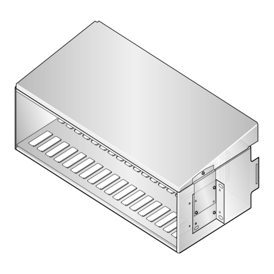
SCP-PCS719-011-01H Overview VERVIEW Plus The PG-Flex ™ 23-inch Central Office Terminal (COT) shelf, PCS-719 List 1A, supports a common ® management or alarm unit, two multiplexer units and up to sixteen universal or integrated PG-Plus Central Office Plus Line Units (COLUs) or up to eight PG-Flex Integrated Central Office Line Units (FICOLUs). -
Page 10: Composite Clock Signals
Overview SCP-PCS719-011-01H OMPOSITE LOCK IGNALS Composite clock signals are a 64 kHz bipolar clock with 8 kHz bipolar violations, that define the bit and byte boundaries of Digital Data Service (DDS) data as it is transferred within a CO. In support of DDS interfaces, PG-Plus defines two composite clock interfaces at the PAU/PMU card slot. -
Page 11: Power
SCP-PCS719-011-01H Overview The following sections identify each connector by type and function. Table 1. PCS-719 Backplane Connectors Connector Description PAU or PMU connector PMX 1 connector PMX 2 connector J4 - J19 COLU connectors. The wire-wrap posts are for the HDSL. - Page 12 Overview SCP-PCS719-011-01H Table 2. COLU #1 (J4) Connector Pinouts Table 3. COLU #2 (J5) Connector Pinouts Pin # Assignment Assignment Pin # Pin # Assignment Assignment Pin # TIP1 RING1 TIP7 RING7 TIP2 RING2 TIP8 RING8 TIP3 RING3 TIP9 RING9 TIP4 RING4 TIP10...
- Page 13 SCP-PCS719-011-01H Overview Table 4. COLU #3 (J6) Connector Pinouts Table 5. COLU #4 (J7) Connector Pinouts Pin # Assignment Assignment Pin # Pin # Assignment Assignment Pin # TIP13 RING13 TIP19 RING19 TIP14 RING14 TIP20 RING20 TIP15 RING15 TIP21 RING21 TIP16 RING16 TIP22...
- Page 14 Overview SCP-PCS719-011-01H Table 6. COLU #5 (J8) Connector Pinouts Table 7. COLU #6 (J9) Connector Pinouts Pin # Assignment Assignment Pin # Pin # Assignment Assignment Pin # TIP25 RING25 TIP31 RING31 TIP26 RING26 TIP32 RING32 TIP27 RING27 TIP33 RING33 TIP28 RING28 TIP34...
- Page 15 SCP-PCS719-011-01H Overview Table 8. COLU #7 (J10) Connector Pinouts Table 9. COLU #8 (J11) Connector Pinouts Pin # Assignment Assignment Pin # Pin # Assignment Assignment Pin # TIP37 RING37 TIP43 RING43 TIP38 RING38 TIP44 RING44 TIP39 RING39 TIP45 RING45 TIP40 RING40 TIP46...
- Page 16 Overview SCP-PCS719-011-01H Table 10. COLU #9 (J12) Connector Pinouts Table 11. COLU #10 (J13) Connector Pinouts Pin # Assignment Assignment Pin # Pin # Assignment Assignment Pin # TIP49 RING49 TIP55 RING55 TIP50 RING50 TIP56 RING56 TIP51 RING51 TIP57 RING57 TIP52 RING52 TIP58...
- Page 17 SCP-PCS719-011-01H Overview Table 12. COLU #11 (J14) Connector Pinouts Table 13. COLU #12 (J15) Connector Pinouts Pin # Assignment Assignment Pin # Pin # Assignment Assignment Pin # TIP61 RING61 TIP67 RING67 TIP62 RING62 TIP68 RING68 TIP63 RING63 TIP69 RING69 TIP64 RING64 TIP70...
- Page 18 Overview SCP-PCS719-011-01H Table 14. COLU #13 (J16) Connector Pinouts Table 15. COLU #14 (J17) Connector Pinouts Pin # Assignment Assignment Pin # Pin # Assignment Assignment Pin # TIP73 RING73 TIP79 RING79 TIP74 RING74 TIP80 RING80 TIP75 RING75 TIP81 RING81 TIP76 RING76 TIP82...
- Page 19 SCP-PCS719-011-01H Overview Table 16. COLU #15 (J18) Connector Pinouts Table 17. COLU #16 (J19) Connector Pinouts Pin # Assignment Assignment Pin # Pin # Assignment Assignment Pin # TIP85 RING85 TIP91 RING91 TIP86 RING86 TIP92 RING92 TIP87 RING87 TIP93 RING93 TIP88 RING88 TIP94...
-
Page 20: Alarm Cutoff
Overview SCP-PCS719-011-01H Alarm Cutoff The shelf backplane provides a wire-wrap pin for connection to an external alarm cutoff circuit. Alarm Contacts The COT shelf provides access to the PAU/PMU alarm relays by way of wire-wrap pins on the COT shelf backplane. -
Page 21: Network Interface
SCP-PCS719-011-01H Overview Network Interface The COT shelf supports RS-232 X.25 interfaces through a backplane-mounted DB25 connector. The rear backplane DB-25 is a female connector wired as a Data Terminal Equipment (DTE) interface. The signals and pin assignments for this connector are listed in Table 18, “PCS-719 Backplane DB-25 Connector Pinouts,”... -
Page 22: Lan Interface
Overview SCP-PCS719-011-01H Figure 5. Null Modem Connection for PCS-719 Backplane LAN Interface The COT shelf supports communications between multiple shelves by means of a 10Base2 BNC LAN connector. This feature requires a PMU installed in the COT shelf. Refer to the PMU documentation for additional information on this interface. -
Page 23: Pau/Pmu Connector
SCP-PCS719-011-01H Overview PAU/PMU Connector J1 on the COT shelf backplane is the 96-pin DIN-type PAU/PMU connector. Table 19, “PAU/PMU 96-Pin DIN-Type Connector,” on page 15 lists the PAU/PMU connector pinouts. Table 19. PAU/PMU 96-Pin DIN-Type Connector Pin # Row A Row B Row C MJRAUDNO... -
Page 24: Pmx Connectors
Overview SCP-PCS719-011-01H PMX Connectors J2 and J3 on the COT shelf backplane are the 160-pin DIN-type PMX connectors. Table 20 lists the connector pinouts for PMX 1 (J2 on the backplane). Table 21, “PMX 2 160-Pin DIN-Type Connector,” on page 17 lists the connector pinouts for PMX 2 (J3 on the backplane). - Page 25 SCP-PCS719-011-01H Overview Table 21. PMX 2 160-Pin DIN-Type Connector Pin # Row A Row B Row C Row D Row E RDATB1 RDATB2 RDATB3 RDATB4 RDATB5 RSIGB1 RSIGB2 RSIGB3 RSIGB4 RSIGB5 TDATB1 TDATB2 TDATB3 TDATB4 TDATB5 TSIGB1 TSIGB2 TSIGB3 TSIGB4 TSIGB5 CLKB1 CLKB2...
-
Page 26: Specifications
Overview SCP-PCS719-011-01H PECIFICATIONS Environmental Operating Elevation –200 ft to 13,000 ft (–60 m to 4,000 m) Temperature –40° F to +149° F (–40° C to +65° C) Operating Humidity 5% to 95% (noncondensing) Compliance NEBS SR-3580 for Level 3 Human Safety UL 1950 for Restricted Access Emissions Radiation and Immunity GR-1089-CORE for Class A Equipment... -
Page 27: Installation And Test
SCP-PCS719-011-01H Installation and Test NSTALLATION AND EQUIRED OOLS AND QUIPMENT The tools and test equipment required for the installation of the COT shelf are: • Wire-wrap tool for .045-inch square pins • No. 2 Phillips screwdriver • Flat-head screwdriver • Wire-strippers •... -
Page 28: Powering The Integrated Systems
Installation and Test SCP-PCS719-011-01H Powering the Integrated Systems Plus Table 22 summarizes the shelf powering requirements and heat dissipation for the PG-Flex COT shelf when it is fully populated with services, a battery voltage of –48.0 V, and with all CO to RT distances at their maximum DSL reach. -
Page 29: Powering The Universal Systems
SCP-PCS719-011-01H Installation and Test Powering the Universal Systems Table 23, “PCS-719 Shelf Power and Heat Dissipation for Universal Systems,” on page 21 summarizes the shelf Plus powering requirements and heat dissipation for the PG-Flex COT shelf when it is fully populated with services, a battery voltage of –48.0 V, and with all CO to RT distances at their maximum DSL reach. -
Page 30: Wiring Access
Installation and Test SCP-PCS719-011-01H PCS-719 CO E NSTALLING THE INTO A QUIPMENT RAME The Network Equipment Building Standard (NEBS) limits the maximum dissipation in a 12-inch deep individual CO equipment frame, with open-faced mounting and natural convection cooling, to 946 W (Watts). Refer to each individual line unit technical practice to determine the maximum number of units that can occupy any bay with the 946 W limit. -
Page 31: Connections
SCP-PCS719-011-01H Installation and Test ONNECTIONS Ground Connections Frame Ground must be connected to provide a discharge path for outside plant protection circuits. Two Frame Ground termination points are provided on the COT shelf. The J22 and TB1 FGND Frame Ground termination points are electrically equivalent. -
Page 32: Redundant Shelf Powering
Installation and Test SCP-PCS719-011-01H The –48 Vdc circuits should be fused according to Table 22, “PCS-719 Shelf Power and Heat Dissipation for Integrated Systems,” on page 20 Table 23, “PCS-719 Shelf Power and Heat Dissipation for Universal Systems,” on page Disconnect both input supply sources before servicing. -
Page 33: Split Shelf Powering
SCP-PCS719-011-01H Installation and Test Split Shelf Powering In this configuration, one half of the shelf is powered from one –48 Vdc source, the other half is powered from another –48 Vdc source. Common equipment circuit cards are powered from both sources. If one power supply should fail, one-half of the shelf maintains power. -
Page 34: Single Source Powering
Installation and Test SCP-PCS719-011-01H Single Source Powering In this configuration, the entire shelf is powered from a single source of –48 Vdc power fused according to Table 22, “PCS-719 Shelf Power and Heat Dissipation for Integrated Systems,” on page 20 Table 23, “PCS-719 Shelf Power and Heat Dissipation for Universal Systems,”... -
Page 35: Audible And Visual Alarm Connections
SCP-PCS719-011-01H Installation and Test Audible and Visual Alarm Connections Use a wire-wrap tool to terminate the alarm leads from the external alarm equipment on the alarm relay wire-wrap field. See Figure 10, “Connecting the Alarm Relays,” on page 28 for the location of the alarm relay wire-wrap field. - Page 36 Installation and Test SCP-PCS719-011-01H Table 24. Alarm Terminations Contact Contact Contact Post Post Post Posts FUNCTION SYSTEM System indicates a critical, major or minor alarm is active on the COT shelf. CRIT VISUAL Indicates a critical alarm. Connect this relay to the critical alarm visual indicator of the CO alarm system.
-
Page 37: Subscriber Connections From Co
SCP-PCS719-011-01H Installation and Test Subscriber Connections From CO Tables 25 through 28 show the assignment of subscriber services from each card slot location to the Telco connectors. Subscriber lines from the CO are connected to the COT shelf by way of 50-pin Telco connectors (P1, P2, P3, and P4). - Page 38 Installation and Test SCP-PCS719-011-01H Table 26. P2 Tip and Ring Pin Assignments COT Shelf COLU Type Connector Shelf Assignments Cardslot PLL-720 PLL-721 PLL-722 PLL-723 PLL-724 PLL-729 PLL-733 PLL-734 Ring POTS1 POTS1 POTS1 POTS UVG1 EBS1 POTS1 P2-26 P2-1 POTS2 POTS2 POTS2 UVG2 EBS2...
- Page 39 SCP-PCS719-011-01H Installation and Test Table 27. P3 Tip and Ring Pin Assignments COT Shelf COLU Type Connector Shelf Assignments Cardslot PLL-720 PLL-721 PLL-722 PLL-723 PLL-724 PLL-729 PLL-733 PLL-734 Ring POTS1 POTS1 POTS1 POTS UVG1 EBS1 POTS1 P3-26 P3-1 POTS2 POTS2 POTS2 UVG2 EBS2...
- Page 40 Installation and Test SCP-PCS719-011-01H Table 28. P4 Tip and Ring Pin Assignments COT Shelf COLU Type Connector Shelf Assignments Cardslot PLL-720 PLL-721 PLL-722 PLL-723 PLL-724 PLL-729 PLL-733 PLL-734 Ring POTS1 POTS1 POTS1 POTS UVG1 EBS1 POTS1 P4-26 P4-1 POTS2 POTS2 POTS2 UVG2 EBS2...
- Page 41 SCP-PCS719-011-01H Installation and Test Table 29. P1 Telco Connector Table 30. P2 Telco Connector Pin # Assignment Assignment Pin # Pin # Assignment Assignment Pin # RING1 TIP1 RING25 TIP25 RING2 TIP2 RING26 TIP26 RING3 TIP3 RING27 TIP27 RING4 TIP4 RING28 TIP28 RING5...
- Page 42 Installation and Test SCP-PCS719-011-01H Table 31. P3 Telco Connector Table 32. P4 Telco Connector Pin # Assignment Assignment Pin # Pin # Assignment Assignment Pin # RING49 TIP49 RING73 TIP73 RING50 TIP50 RING74 TIP74 RING51 TIP51 RING75 TIP75 RING52 TIP52 RING76 TIP76 RING53...
- Page 43 SCP-PCS719-011-01H Installation and Test Table 33. P5 Telco Connector Pin # Assignment Assignment Pin # 4WTXR1 4WTXT1 4WRXR1 4WRXT1 4WTXR2 4WTXT2 4WRXR2 4WRXT2 4WTXR3 4WTXT3 4WRXR3 4WRXT3 4WTXR4 4WTXT4 4WRXR4 4WRXT4 4WTXR5 4WTXT5 4WRXR5 4WRXT5 4WTXR6 4WTXT6 4WRXR6 4WRXT6 4WTXR7 4WTXT7 4WRXR7 4WRXT7...
-
Page 44: Composite Clock Connections
Installation and Test SCP-PCS719-011-01H Composite Clock Connections This step is required only if provisioning for DDS circuits. Termination resistors (TERM1 and TERM2) are located below the composite clock wire-wrap pins to provide the correct termination on the composite clock. To connect the clock leads from the Central Office Timing Source Generator to the COT shelf backplane: Connect the first clock pair from the timing source generator to the CC1TIP and CC1RING. -
Page 45: Dsx-1 Connections
SCP-PCS719-011-01H Installation and Test DSX-1 Connections This step is required only if the PCS-719 is to support IDLC applications. The input (side 1) DSX-1 wire-wrap connections include 100 Ω line termination resistors on the PCS-719 backplane. Each DSX-1 circuit is connected to the PCS-719 backplane (see Figure 12, “DSX-1 Backplane Terminations,”... -
Page 46: Hdsl Wiring
Installation and Test SCP-PCS719-011-01H HDSL Wiring J4 - J19 on the PCS-719 backplane correspond to COLU slot numbers LU1 to LU16. Figure 13, “Connecting the HDSL Pairs,” on page 39 shows HDSL connections for J4 and J5. The wire-wrap pin labels for J4 - J19 correspond to the COLU slot number (LU1, LU2, etc.). - Page 47 SCP-PCS719-011-01H Installation and Test Table 34. PCS-719 HDSL Connections COT Shelf Central Office Line Unit Card Slot HDSL Terminations Single 4/6 Ch. COLU Dual 2/4/6 Ch. ICOLU Single 24 Ch. ICOLU LU 1 DSL_A – 1 1 – HDSL 1 – HDSL (1A) 1 –...
-
Page 48: Test Connection
Installation and Test SCP-PCS719-011-01H Test Connection This step is required only if the PCS-719 is to support IDLC applications. The Test connection is located to the left side of the pins labeled TSTTIP and TSTRING on the lower right side of the PCS-719 backplane, as shown in Figure 14, “Connecting the Test Pair,”... -
Page 49: External Aco Connection
SCP-PCS719-011-01H Installation and Test External ACO Connection The Alarm Cut Off (ACO) connection is located to the left handed side of the pin labeled EXT ACO as shown in Figure 15, “Connecting the External ACO Switch,” on page 42. To control the ACO remotely, connect the ACO to GROUND through a Normally Open, momentary contact switch. -
Page 50: Abbreviations
Abbreviations SCP-PCS719-011-01H BBREVIATIONS Alarm Cut Off American Wire Gauge Central Office COLU Central Office Line Unit Central Office Terminal Digital Data Service Digital Signal One Data Terminal Equipment FICOLU PG-Flex Integrated Central Office Line Unit HDSL High-bit-rate Digital Subscriber Line Light-Emitting Diode NEBS Network Equipment Building Standard... -
Page 51: Product Support
SCP-PCS719-011-01H Product Support RODUCT UPPORT ECHNICAL UPPORT ADC Technical Assistance is available 24 hours a day, 7 days a week by the contacting ADC Customer Service Engineering group at: 800.638.0031 or 714.730.3222 Telephone: The 800 telephone support line is toll-free in the U.S. -
Page 52: Returns
Product Support SCP-PCS719-011-01H ETURNS To return equipment to ADC: Locate the number of the purchase order under which the equipment was purchased. To obtain a return authorization number, you need to provide the original purchase order number to ADC’s Return Material Authorization (RMA) Department. -
Page 53: Fcc Classa Compliance
SCP-PCS719-011-01H Product Support FCC C LASS OMPLIANCE This equipment has been tested and found to comply with the limits for a Class A digital device, pursuant to Part 15 of the FCC Rules. These limits are designed to provide reasonable protection against harmful interference when the equipment is operated in a commercial environment. - Page 54 Corporate Office 14402 Franklin Avenue Tustin, CA 92780 Tel: 714.832.9922 Fax: 714.832.9924 For Technical Assistance: 800.638.0031 714.730.3222 &!%$& 1183768...
Need help?
Do you have a question about the PairGain PG-FlexPlus PCS-719 and is the answer not in the manual?
Questions and answers