Advertisement
Note: please go to download latest instruction manuals!
Note 2: please read the manual carefully before using!
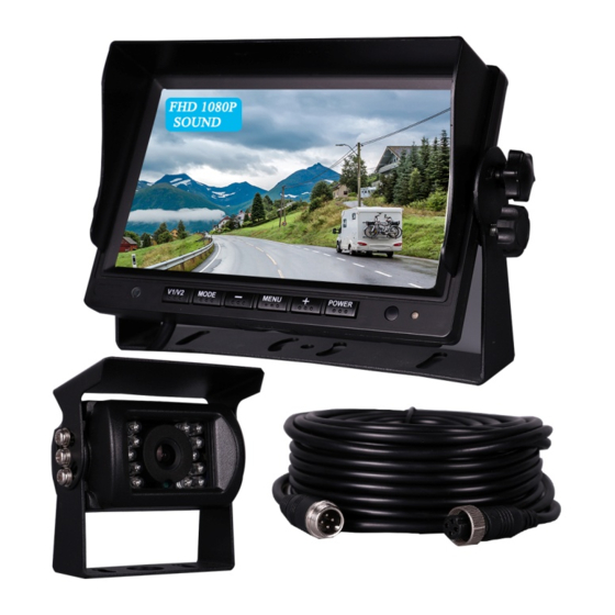
What's in the Box?

Monitor x 1

U-bracket x 1

Power cable x 1

Camera x 1
")
Extension cable (50ft) x 1

Remote controller x 1

Angle adjustment screws x 4

Self tapping screws x 4

Instruction manual x 1
Note: Details may change based on item configuration
FEATURE
- Camera built-in Microphone & monitor built-in speaker: You can get the video sound while driving or parking.
- Multi-function and Multi-channel Signal Input - Equipped with independent green reversing trigger line.
- The centralized power cord is powered by the power supply on the fuse box in cab, eliminating the tedious steps of disassembling and installing the tail lamp.
- System can be installed to turn on only when vehicle is in reverse, or wired for continuous viewing.
- Best fit for heavy-duty vehicles: RV, Motorhome, Large truck, travel trailer, box truck, etc.
- Meets FCC/CE standards
PARTS IDENTIFICATION

- Sun Shield
- Digital Color LCD Screen
- Reserved
- V1/V2 button: switch among cameras
- MODE button: rotate image
- button: decrease/down arrow
- MENU button: setting volume, brightness...
- + button: increase/up arrow
- POWER button: turn on/off and standby
- Power Indicator: normal/standby mode
- Remote Control

- Loudspeaker
- U-bracket socket
- Duckfoot bracket socket

- Protective shield
- 18 Infrared LEDs
- FHD Lens
- Auto Light Sensor
- Protective rubber ring
- Microphone
- U-bracket
INTRODUCTION
This manual contains instructions to make the installation of the camera and monitor easier. The color backup camera system is a supplement to standard rear-view mirror systems, and will provide additional rear-view vision when installed and maintained properly. It is not intended in any way to be a substitute for careful and cautious driving.
GETTING STARTED
TEST THE SYSTEM
We recommend doing a benchmark test before installation to insure that all components are working properly. To ensure the system works properly after installation, all components should be tested and checked before installation.
Firstly, refer to the what's in the box page to check whether the component is missing. We do not rule out that some components may be damaged in the case of violent loading and unloading during transportation. If so, please contact us in time.
Secondly, connect the power cable(9 pin connector) to the monitor, the positive and negative terminals to 12-32v voltage, then the power indicator will turn blue and all the buttons into blue backlight, indicating the successful test of the display, can work normally.
Finally, connect 4-pin connector(the other end of the power cable)to the backup camera, restart the power supply of the monitor, and the corresponding channel image will appear, If display normally, so the backup camera is working properly. If not please refer to the troubleshooting.
Note: The monitor can only display the image of the camera of the corresponding channel, if your camera is connected to the AV1 channel, please switch the monitor to AV1.
BEFORE BEGINNING INSTALLATION
 As the camera needs to be fixed on the vehicle, it may need to drill a hole on your car, before drilling please measure the size of boreholes and check that no cable or wiring is on the other side of the wall.
Keep all cables away from hot or moving parts and electrical noisy components.
Please clamp all wires securely to reduce the possibility of them being damaged while vehicle is in use.
INSTALLATION GUIDE
SYSTEM CONNECTION DIAGRAM

NOTE: If you run the system (reverse only), we recommend connecting the camera to channel AV2 and connect the green wire to backup light wire or backup beeper wire. If you run the system consistently (driving+parking+reversing), we recommend connecting the camera to channel AV1 and ignore this green wire.
RECOMMENDED INSTALLATION LOCATION
Camera: close to rear marker lights, centered on vehicle.
Monitor: dashboard
CABLE CONNECTION
RED wire to ignition hot (+) 12-32 volts.
BLACK wire to ground (-) (please use a chassis ground post).
GREEN trigger wire is for CH2 camera channel.
Connects green trigger wire to backup light wire or backup beeper wire. This connection is needed to activate the monitor when putting the vehicle into reverse.
POWERED BY CIRCUIT FUSE
Firstly, recommended and connect the RED Wire(ACC+) to the fuse switch.
Secondly, find the car circuit fuse box under your car cab.
Finally, according to the labels on the fuse hardwire to find the corresponding power fuse and connect the corresponding line (voltage must between 12-32V).
Note: If connecting power directly to battery, the camera is always ON and therefore can drain battery. Therefore it is recommended to connect power to an ignition switched accessory power source.
INSTALLATION CAMERA
Firstly, find the best installation position to install backup camera on your vehicle, e.g. close to rear marker lights, centered on vehicle.
Secondly, remove the camera U-bracket, mark the hole position with a marker pen, then drilling, after the hole is finished, route the terminal wire of the camera through it and install the screw of the backup camera.
Finally,adjust the best angle.
INSTALLATION MONITOR
Firstly, Find the best installation position to install monitor in your vehicle.
Secondly, Remove the screw around then take out the monitor. Put U-bracket to the right place and adjust angle, prepare 2 screws.
Thirdly, Locking the bracket by screws. Put the monitor into bracket and locking it.
Finally, adjust the best angle to allow optimum driver viewing comfort by themself.
OPERATION GUIDE
REMOTE CONTROL
Power button
Video select button
Left arrow(Positive/increase) button
Menu button
Right arrow(Negative/decrease) button
Mode select button: rotate flip image/normal/mirror image setting
FUNCTIONS OPERATE
V1/V2 button: switch CH1 and CH2 channel camera.
Mode button: rotate flip image/normal/mirror image setting.
Power button: turn on/off and stadnby.
Menu button press 1 times: enter brightness adjust mode, press +/- to increase/ decrease the value, wait 10 seconds to exit setup mode, valid value is 0—40,factory default value is 20.
Menu button press 2 times: enter contrast adjust mode, press +/- to increase/ decrease the value, wait 10 seconds to exit setup mode, valid value is 0—40,factory default value is 20.
Menu button press 3 times: enter color adjust mode, press +/- to increase/ decrease the value, wait 10 seconds to exit setup mode, valid value is 0—40,factory default value is 20.
Menu button press 4 times: enter language adjust mode, press +/- to increase/ decrease the value, wait 10 seconds to exit setup mode, valid value is English, Francais...,factory default value is English.
Menu button press 5 times: enter default setting mode, press +/- to increase/ decrease the value, wait 10 seconds to exit setup mode, Notes: valid item is brightness, contrast, color, volume, ruler setting only, invalid item is language RLUD,VCOM.
Menu button press 6 times: enter volume adjust mode, press +/- to increase/ decrease the value, wait 10 seconds to exit setup mode, valid value is 0—40,factory default value is 20.
Menu button press 7 times: enter RLUD adjust mode(normal/mirror flip rotate image), press +/- to increase/ decrease the value, wait 10 seconds to exit setup mode, valid value is 1,2,3,4, this selection rotate/flip each camera image individually both horizontally and vertically, This allows for a correct image of front/rear camera, e.g. 4--rear camera, 3--front camera, effect individually both CH1and CH2.
Menu button press 8 times: enter VCOM adjust mode, press +/- to increase/ decrease the value, wait 10 seconds to exit setup mode, valid value is 0—40,factory default value is 20.
Menu button press 9 times: enter ruler setting adjust mode(parking guideline), press +/- to increase/ decrease the value, wait 10 seconds to exit setup mode. Note: valid setting for CH2 channel only, invalid settingfor CH1 channel.
Menu button press 10 times: enter version check mode, wait 10 seconds to exit setup mode, reserve only.
Parking guideline setting:same as "Menu button press 9 times".
Mirror image setting: same as "Menu button press 7 times".
SPECIFICATION & DIMENSION
Camera
| Image Sensor | 1/3" Color CMOS |
| TV System | NTSC(1080P/30fps) |
| Effective Pixels | 1920(H)x1080(V) |
| Horizontal Sync Frequency | 33.750KHz |
| Vertical Sync Frequency | 30Hz |
| Electronic Shutter | 1/30~1/60 Seconds |
| Scanning System | Progressive Scanning |
| Sync System | Internal |
| Resolution | 1080P |
| Video Output | AHD,1.0Vp-p, 75Ohm |
| White Balance | Auto |
| Power Supply | DC12V |
| Waterproof rating | IP69K |
| Viewing Angle | 120˚ |
| Audio | Yes |
| Minimum lllumination | 0 Lux with IR ON |
| Night vision distance | 8-10m |
| Image mode | Mirror image |
| SMART IR-CUT | Yes |
| Operating Temperature | -30~70,RH90% MAX |
| Storage Temperature | -40~80,RH90% MAX |
Monitor
| LCD Size | 7" lcd color monitor with digital IPS Panel |
| Resolution | 1024x3(RGB)x600 |
| Brightness | 550cd/m2 |
| Contrast | 600:1 |
| View angle | U/D:85˚;L/R:85˚ |
| Power Supply | DC9-36V |
| Power Consumption | about 6W |
| Support Audio intput hannel | CH1, CH2 |
| Built-in Loud Speaker | Yes (1W) |
| Screen Mode | 16:9 |
| Support Video System | 1080P/720P/CVBS auto detection |
| OSD menu, Remote Control | Mirror/Normal Flip Image, Guideline ON/OFF,Brightness, Contrast, Color, volume |
| Outline Dimension | 4.6"(H)x7"(L)*8.2"(D) |
Extension Cable
| Length | 50ft |
| Feature1 | Pure copper wire |
| Feature2 | Double shielding: tinfoil wrap up and copper wire winding |
TROUBLESHOOTING
If you have any questions about this product, Please send us an mailbox above!
Monitor will not power-up
(the power indicator LED lights is always off)
Check fuse
Check 12v+ to monitor
Check ground connection
Check this product within the voltage range(12-32V) specified.
No signal/blue on monitor screen
Do a hard reset, unplug all cables, leave out for 1 minute and then re-connect them.
Check to ensure that the connection to the camera is tight.
Verify camera cable is plugged into port labeled backup camera
Verify that the red positive trigger on power harness cable is put to power 12v+.
No image on screen
Verify camera is on correct camera input
Verify cable is connected to monitor
Verify camera is connected to cable
Connect known working camera and cable to monitor.
No audio on camera
Verify volume setting
Verify chosen camera has audio function.
Verify chosen extension cable has audio wire
Wrong normal/mirror image setting
Verify RLUD(normal/mirror flip rotate image) setting, e.g. mirror image: rear camera; normal image: front/side camera.
Verify chosen camera has mirror
No parking guideline on camera
Verify ruler setting is on
Verify chosen camera is CH2 channel, invalid for CH1 channel
Verify and make sure if the green reverse trigger wire is properly connected to backup light wire or backup beeper wire.
Verify and put the vehicle into reverse.
Documents / ResourcesDownload manual
Here you can download full pdf version of manual, it may contain additional safety instructions, warranty information, FCC rules, etc.
Advertisement
Need help?
Do you have a question about the 1080P Backup Camera and is the answer not in the manual?
Questions and answers