
Related Manuals for VENUS CONCEPT MP2

Summary of Contents for VENUS CONCEPT MP2
- Page 1 USER MANUAL INTERNATIONAL Venus Freeze (MP) User Manual Effective date: 01.06.2012, P/N: FREU802442E...
- Page 2 Venus Concept Ltd. is believed to be accurate and reliable. However, Venus Concept Ltd. assumes no responsibility for its use. No license is granted by its implication or otherwise under any patent or patent rights of Venus Concept Ltd.
-
Page 3: Table Of Contents
Table of Contents Chapter 1 - Before You Start ................1 Glossary of Symbols Used in this Manual ..............1-1 S/N Label ........................1-2 Warning ........................1-2 Chapter 2 - Introduction ................2-1 View of Venus Freeze (MP)² System ................. 2-1 System Description .................... -
Page 4: Glossary Of Symbols Used In This Manual
1. Before You Start Glossary of Symbols Used in this Manual The following are symbols that you will find throughout this operating manual and their meanings: WARNING sign: The information stated where you will see this symbol is extremely important and must be noted! Provides general information that is important to keep in mind. -
Page 5: S/N Label
Consult Instruction for Use. System that includes RF transmitters or that applies RF electromagnetic energy for diagnosis or treatment. S/N Label Figure 1-2, Venus Freeze (MP) Figure 1-1, Venus Freeze (MP) Black - Serial Number Label White - Serial Number Label WARNING Read the User Manual instructions carefully before installing or using the System to become familiar with all safety requirements and operating procedures thereby... -
Page 6: Introduction
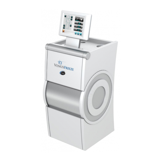
2. Introduction View of Venus Freeze (MP) System Figure 2-1 Front Figure 2-2 Back Panel of Venus Freeze (MP) of Venus Freeze (MP) White or Black White or Black a. a ) Octipolar Applicator (detachable accessory) or a ) Octipolar 2.0 Applicator - White or Black. -
Page 7: System Description
System Description The Venus Freeze (MP) is a non invasive medical aesthetic device with a solution for face and body contouring via Skin Tightening, Circumferential Reduction, Cellulite Reduction and Wrinkle Reduction. Venus Freeze (MP)² is powered by (MP) (MP)² technology is comprised by Magnetic Pulse and Multi Polar RF (Radio Frequency) that are being transmitted through body and facial Applicators called “Octipolar”/”Octipolar 2.0”... -
Page 8: Introduction
3. Safety This chapter describes safety issues regarding the use and maintenance of the System, with special emphasis on electrical safety. Please carefully read this chapter and be familiar with all of its safety requirements and operating procedures prior to operating the System. Introduction The System is designed for a safe and reliable treatment when used in accordance to proper operating and maintenance procedures as outlined in this operating manual. - Page 9 Do not abuse, sit or lean on the system. Venus Freeze (MP)² System should be kept out of the reach of Children. Do not allow the Octipolar/Octipolar 2.0 or Diamondpolar Applicators to come in contact with metal elements - this could damage the (MP) electrodes.
-
Page 10: Electrical And Mechanical Safety
Electrical and Mechanical Safety Keep all covers and panels of the System closed. Removing the covers/panels will not only create a safety hazard but will also affect your service agreement. Keep your hands away from the Applicators during the System start-up. ... -
Page 11: Equipment List
4. System Installation The System is designed for installation in an medical aesthetic environment. To install the System, please follow the instructions listed below: 1. Inspect the original packaging prior to opening to insure that during transportation, no damage was done to the outer carton layer and the anti-shock sticker (Damaged = Red indicator). -
Page 12: Electrical Requirements
Electrical Requirements The System can automatically accommodate the most of the local mains voltage. Specifically, the System can be energized of the mains voltage as follow: Single phase 100-240V~ ; 50-60Hz. 10A. For continued protection against fire, only fuses that are defined on the System label can be insulted in the System. - Page 13 If the shape of the floor has the angle of 100 degrees or more than System should be transported with backside handle forward. Tilt the System toward the back using its backside handle making sure you have a firm hold of the front of the System and slowly push or pull it, always carefully lifting it and placing it on its backside handle for transportation.
-
Page 14: Turning The System On/Off
5. Operating the System Turning the System On/Off Before turning the System “ON”, verify that the power cord is connected to the inlet located on the rear panel of the system and to the main power outlet. Switch on the system by turning the “ON/OFF” button located in the rear panel of the system to its “ON”... -
Page 15: Menu Screen Option
Menu Screen Options The Treatment Screen is the system main screen (figure 5-2). Treatment is initiated on this screen. The Tools screen is accessed from the Main screen/Treatment screen. In order to perform a treatment, the operator needs to follow the steps below: 1. -
Page 16: Treatment
Treatment Selecting Suitable Applicator Before the treatment, the operator must select the desired Applicator, according to the size of the treatment area. The Octipolar/Octipolar 2.0 Applicator is used for the treatment of large areas as it has more coverage. The Diamondpolar Applicator is used for the treatment of smaller areas. - Page 17 Adjusting (MP) Output Power (MP) Output Power is measured in percents of Maximum power. It is adjusted by pressing the “+” & “-“ buttons located on the screen next to the (MP) button (figures 5-5 & 5-6). Adjustments are in one-percent increments. (MP) Output Power is between 0-100 percent, whereas 0% is equivalent to zero (no) RF output, and 100% is equivalent to 150W RF output (maximum RF output of the...
- Page 18 Adjusting Treatment Time Treatment Time is measured in minutes. It is adjusted by pressing the “+” & “-“ buttons located on the screen next to the clock icon (see Figures 5-7 & 5-8). Adjustments are in one-minute increments. Treatment Time is set between 0-30 minutes. This parameter can be increased and / or decreased during the treatment.
- Page 19 Changing the parameters of the Memory buttons is done by setting the required parameters and pressing the selected Memory button for 10 sec. consecutively (similar to setting radio stations in car radios). After new parameters were successfully stored in a Memory Button, an icon of a diskette will appear on the screen (figure 5-10, circled in red).
- Page 20 The Countdown Timer (figure 5-12) begins countdown when treatment is initiated and beeps when timer is zeroed. Pressing the Interval Timer button (figure 5-12, circled in red) will synchronize the Countdown Timer with the Interval Time. Figure 5-11: Treatment Screen Interval Timer Button Interval Time Countdown Timer...
-
Page 21: Initiating (Starting) Treatment, Pausing And Stopping A Treatment
Initiating (Starting) Treatment, Pausing and Stopping a Treatment Once Treatment Time and (MP) Output Power parameters are set, the operator should hold the selected Applicator and press the Start button located in the lower right corner of the Treatment Screen (figure 5-13, circled in red). This will emit RF via the selected Applicator, and the treatment can begin. - Page 22 During the treatment, pressing the Pause button (figure 5-15, circled in red) will pause the treatment. When paused, the treatment parameters will not be reset, but the system will not emit RF from the Applicators. The Pause button will turn red. Pressing the Start button again will continue the treatment.
-
Page 23: Tools
When pressing the Tools button (figure 5-18, circled in red) in Treatment screen, the Tools screen will appear (figure 5-19) enabling operator to personalize the system, and enabling a Venus Concept technician to update the system software, calibrate the screen and more. - Page 24 Setting the Volume Level of the System Speakers Pressing the Volume button in the Tools Screen (figure 5-21, circled in red) will open a Volume Screen, enabling the operator to set the volume of the system’s speakers. Volume is defined in percentage between 0-100 (whereas 100% indicates maximum volume).
- Page 25 Set Login Code In order to change the Login Code, the operator has to press the Set Login Code button in Tools screen (see Figure 5-23, circled in red). The Login Code is changed in three steps, using three screens: I.
- Page 26 Logout Pressing the Logout button (see Figure 5-27, circled in red) will lock the system and prevent unauthorized access. The Login Screen will appear, requiring operator to re- enter his Login code. Figure 5-27: Tools Screen - Logout button Venus Freeze (MP) User Manual Effective date: 01.06.2012, P/N: FREU802442E 5-13...
- Page 27 Set Auto Logout Time Pressing the Set Auto Logout Time button in Tools Screen (figure 5-28, circled in red) will open a Set Auto Logout Time Screen, enabling operator to set the time after which the system will logout automatically if the screen has not been activated. The Auto Logout Time is set between 0:15-4:00 hours, and adjusted by pressing the “+”...
- Page 28 Technician Mode The Technician Mode button is located in the Tools screen (figure 5-32) and should be operated by Venus Concept authorized technicians only. It is password protected, and cannot be accessed. Figure 5-32: Tools Screen – Technician Mode button...
- Page 29 Activation Period The Activation Period is an optional feature of the Venus Freeze system. This feature allows system operation for a limited period, referred to as “Activation Period”. If the Activation Code button (a green button) appears on the Tools screen (figure 5- 33 &...
- Page 30 Figure 5-35: Tools Screen – Activation Period is OFF Expiration Date: A week before the Expiration Date, a message will appear on the screen indicating: “Your Activation Period is About to Expire. Please contact your area CSA to receive your new activation code. (Expiration Date: MMM-DD-YYYY” )(figure 5-36). After Expiration Date warning message is over, a message will appear indicating: “Your Activation Period Has Expired.
- Page 31 “Please Enter Activation Code (Key Number: XXXX)” (see Figure 5-40). At this point operator is required to contact the local Venus Concept office and provide the 4-digit-key that appears on the top of the screen (e.g. 5E03) (figure 5-38, circled in red).
- Page 32 The office will then supply a 16-digit Activation Code. Operator should enter the code (followed by pressing the Confirm button). Entering the Activation Code correctly will re-enable system operation. Figure 5-40: Expiration Date Venus Freeze (MP) User Manual Effective date: 01.06.2012, P/N: FREU802442E 5-19...
-
Page 33: Exclusion Criteria
6. Treatment Procedures Exclusion Criteria Active Inflammation and/or Infection in the Treated Area. Current or History of Cancer & Premalignant Condition. Degenerative neurologic diseases. Diseases Stimulated by Heat, (such as recurrent Herpes simplex in the treatment area). - Page 34 1 Jar of Pure Glycerin (liquid for face and gel for body). Infrared Thermometer. Weight Scale (Tracking tools to follow the client’s progress). Measuring Tape (Tracking tools to follow the client’s progress). Camera & Tripod (Tracking tools to follow the client’s progress). Clinical Data Management ...
-
Page 35: Genera Treatment Information
Treatment documents should be kept with information like Body Weight and specific body measurements should be taken before the first treatment. Again to ensure consistency in the measurement of the clients, guidelines should be set on where these measurements should be taken to make sure it is done the same way each time. -
Page 36: Body Treatments
During the procedure, ensure that you are gently pressing the electrodes of either the Octipolar/Octipolar 2.0 or Diamondpolar Applicator towards the skin, making sure all electrodes are in contact with the skin at all times. Applicator movements should be performed in form of “8’s”, circles, elliptical or lifting movements. - Page 37 Recommended Body Treatment Method Figure 6-1, Arms Treatment Method Figure 6-2, Abdomen Treatment Method Figure 6-3, Buttocks Treatment Method Figure 6-4, Thighs Treatment Method Venus Freeze (MP) User Manual Effective date: 01.06.2012, P/N: FREU802442E...
-
Page 38: Face & Neck Treatments
Face & Neck Treatments The procedure consists 2 Phases - Follow phase I and II for each of the 6 treated zones of the face (Figure 6-5), separately: Phase I - increase skin temperature of the treated zone from baseline (~32° ) to the end point (at least 39°... - Page 39 Recommended Face & Neck Treatment Method Figure 6-6, Forehead Figure 6-7, Periorbital Treatment Method Treatment Method Figure 6-8, Cheeks Figure 6-9, Perioral Treatment Method Treatment Method Figure 6-10, Neck Treatment Method Venus Freeze (MP) User Manual Effective date: 01.06.2012, P/N: FREU802442E...
-
Page 40: Cleaning The System
7. Maintenance This chapter describes the routine maintenance procedures users should perform: cleaning the various Apparatuses. All other service/maintenance procedures are to be performed by the company’s authorized service personnel ONLY! For continued protection against fire, replace the fuse ONLY with one of the same type and rating as recommended in this user manual in chapter 9. -
Page 41: Troubleshooting
8. Troubleshooting Failure Correction Check the power cable. Make sure that the Plug No Power cable is inserted into both the wall socket and the System inlet. If the cable is connected properly and still there is no power, contact your local distributor. - Page 42 Failure Correction Restart system (turn system off for couple of minutes Touch Screen and then turn System on). Does Not Respond If the screen still does not respond, contact your local distributor. In the event that you switch “ON” the system and Fuse is blown nothing appears on the screen and at the same time the fans located in the rear panel of the system are...
- Page 43 Failure Correction Restart system (turn system off for couple of minutes message: and then turn System on). "The Machine is If the message still appears, contact your local Locked - Please distributor. Contact Your" appears on the screen Set treatment time and then press the start button to ...
- Page 44 Failure Correction Re-enter login code. message: If you cannot remember your login code you can use "Wrong Login the master code "A1B2C3D4" in order to login but Code - Please Try then, it is recommended that you'll set your own Again"...
-
Page 45: Technical Specifications
9. Technical Specifications Technical Specification & Configurations Input Voltage 100-240V AC, 370VA, 50-60Hz. Max 5A Output RF Frequency 1MHz. Fuse T5A, 250V Max RF Output Power 150W (MP) Applicators Octi-Polar 8x(MP) synthesizers Octi-Polar 2.0 8x(MP) synthesizers Diamond-Polar 4x(MP) synthesizers Operation Mode: (MP) Multi Polar Magnetic Pulse Output voltage 130V @ Rated Load... -
Page 46: Manufacturer Warranty
10. Manufacturer Warranty The Company warrants that the product shall be free from defects in materials and workmanship for a period of 1 (one) year from the date of shipment by the Distributor to the purchaser, provided however that in no event shall any warranty extend more than 15 months from the date it was delivered to the local distributor.
Need help?
Do you have a question about the MP2 and is the answer not in the manual?
Questions and answers