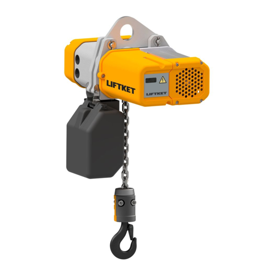
Summary of Contents for Liftket STAR LIFTKET VFD
- Page 1 OPERATING INSTRUCTIONS - Supplement STAR LIFTKET VFD | Electric chain hoists MADE IN GERMANY...
- Page 2 Please do not use the electric chain hoist before all operators have carefully read and understood this manual and signed the form on the rear cover. LIFTKET Hoffmann GmbH Dresdener Straße 64-68 04808 Wurzen / Germany +49-3425-89 24-0 +49-3425-89 24-99 ...
-
Page 3: Table Of Contents
Contents General information ..............................5 Technical Overview ..............................5 Operating Voltage / Control Voltage ........................5 VFD Layout ................................5 Operating of the VFD Electric Chain Hoists......................5 Selection of the operating mode ..........................6 Reduce Speed Mode ..............................8 Hold Speed Mode ..............................9 Setting the Frequency Inverter ..........................10 3.4.1 Keys for Setting .............................. -
Page 5: General Information
1 General information The supplement to the operating instruction for electric chain hoists with frequency inverter (VFD series) is only valid in con- nection with the main operating instruction for electric chain hoists. It only describes the specific operation and possible fault messages of the electric chain hoists with frequency converter. -
Page 6: Selection Of The Operating Mode
3.1 Selection of the operating mode There are different versions of the PCB on the brake side in the electric chain hoist. Board 29 HIDA0 AE2FU Switch position Operating mode Dip switch 1 Dip switch 2 Board marking Reduce speed Mode Dip switch 1 must be set to 'red.'. - Page 7 Board 29 HIDA0 AE3FU Switch position Operating mode Dip switch 1 Dip switch 2 Board marking Reduce speed Mode with Soft Stop Dip switch 1 must be set to ‚red.'. Dip switch 2 must be set to ‚digi.'. Board marking Reduce speed Mode with Quick Stop Dip switch 1 must be set on ‚red.'.
-
Page 8: Reduce Speed Mode
3.2 Reduce Speed Mode In Reduce Speed Mode, the maximum achieved lifting speed can be reduced to 5 Hz. As a result, a cautious settling of the load or a gentle approach to the top hook position is possible. Lifting in Reduce Speed Mode Operation of button Lifting Function Press on 1... -
Page 9: Hold Speed Mode
Depending on the gearbox, the maximum possible lifting and lowering speeds are electronically Note: limited at 24 m/min. Electric chain hoists with a nominal speed of more than 18 m/min at 50 Hz are decelerated be- fore reaching the 90 Hz or 100 Hz mark. 3.3 Hold Speed Mode In Hold Speed Mode, any other constant frequencies or speeds can be used in addition to the constant 50 Hz and 100 Hz frequencies. -
Page 10: Setting The Frequency Inverter
Load Maximum frequency [Hz] Full load Without load Partial load 50 - 90 Table 10: Maximum frequency when lowering in Hold Speed Mode Depending on the gearbox, the maximum possible lifting and lowering speeds are electronically Note: limited at 24 m/min. Electric chain hoists with a nominal speed of more than 18 m/min at 50 Hz are decelerated be- fore reaching the 90 Hz or 100 Hz mark. -
Page 11: Adjustable Parameters
3.4.2 Adjustable parameters The following parameters can be set: Parameter Parameter Function Factory setting Parameter Remarks group number values Acceleration ramp Lifting 1 … 10 Values < 3 can lead to error messages Deceleration ramp Lifting 1 … 10 Acceleration ramp Lowering 1 …... -
Page 12: Possible Fault Messages
Possible fault messages All messages are shown on the display of the electric chain hoist on the front of the control cap. A fault can be reset by switching off the mains or by emergency stop. The display of the control unit must have gone out before the power is switched on again. - Page 13 Fault Description Cause Remedy message brake error brake does not operate check brake and braking voltage check 16-pole flat cable check brake relay on the PCB inverter over-temperature inverter temperature >68°C reduce duty cycle / switches per hour / load high ambient temperature check ambient temperature intermediate circuit voltage <342VDC...


Need help?
Do you have a question about the STAR LIFTKET VFD and is the answer not in the manual?
Questions and answers