Table of Contents
Advertisement
Quick Links
Advertisement
Table of Contents

Subscribe to Our Youtube Channel
Summary of Contents for Inaxsys Incomlink INC-3URX-256
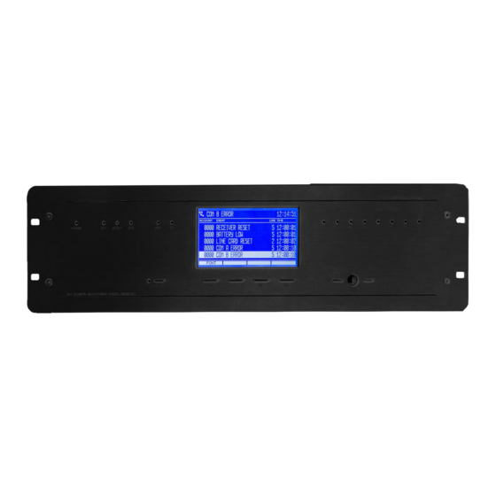
- Page 1 Incomlink | INC-3URX-256 Installer Manual...
-
Page 2: Table Of Contents
CONTENT 1. INTRODUCTION........................3 2. SYSTEM STRUCTURE......................3 2.1 CPM card..........................3 2.2 LC telephone line card (optional)..................4 2.3 RC radio receiver card (optional)..................4 2.4 PWR power supply card.......................4 2.5 IP card (optional)........................4 2.6 Monitoring software compatibility..................5 3. FIRST STEPS..........................5 4. INSTALLATION.........................6 Mounting the receiver unit......................6 Printer connection........................6 PC connection..........................6 CPM central processing card backside connectors..............7... -
Page 3: Introduction
1. INTRODUCTION Thank you for choosing our product. This modern and reliable monitoring receiver not only guarantees the highest level of security, but also it is a useful colleague in the life of every monitoring company, because of its user-friendly handling and intelligent functions. -
Page 4: Lc Telephone Line Card (Optional)
2.2 LC telephone line card (optional) Receiver has 8 slots to connect LC telephone line cards. LC line cards can monitor one telephone line. Each telephone line card have memory to store up to 500 events or caller ID. Caller ID function is built in, the caller telephone number is stored and can be transmitted to monitoring computer. -
Page 5: Monitoring Software Compatibility
2.6 Monitoring software compatibility The device can work with the most generally used monitoring software packages. The device can work with the most generally used monitoring software packages: SURGARD receiver type should be selected as receiver type. 3. FIRST STEPS Please unpack the device carefully and please check is there any damage on that caused by transport. -
Page 6: Installation
4. INSTALLATION Mounting the receiver unit INC-3URX-256 is manufactured in a 3HE height 19” table housing. In addition it can be mounted to a standard 19” rack case by means of the holes in front board. Note: The table stands might be folded up in case of installation to a rack case. Note: LCD display is planned to be well seen in table usage. -
Page 7: Cpm Central Processing Card Backside Connectors
CPM central processing card backside connectors RESET – Hardware reset button. COM A – Default communication port for PC connection. COM B – Reserve communication port for PC connection (or for external receiver). LPT – Parallel printer port. TCP/IP – Ethernet connector for IP monitoring and for remote programming. USB A –... -
Page 8: Pwr Power Supply Card Backside Connectors
PWR power supply card backside connectors For device installation connect the external voltage to the PWR card 16.5 V AC terminals and the battery to the „BATTERY 1 +” and „BATTERY 1 –” connectors. The receiver executes a self-test after connecting the power supply and it detects system components (optional LC line cards, RC radio receiver card, IP card). -
Page 9: Lc Telephone Line Card Backside Connectors (Optional)
LC telephone line card backside connectors (optional) LC line card is suitable to receive analog (PSTN) telephone line. Connect the telephone line into the “LINE/SET” RJ11 connector at the backside of the line card. In case of ISDN line use one of the analog line outputs of ISDN NT box. For two-way audio connection the telephone set should be connected to “LINE/SET”... -
Page 10: Rc Radio Receiver Card Backside Connectors (Optional)
RC radio receiver card backside connectors (optional) RC radio receiver card can handle two independent radio channels. Channel “A” is usually supplied with built in radio (or external radio for special request). Channel “B” only can be used with an external radio unit. If the channel “A” is supplied with built in radio (RTX 2U2), only the antenna should be connected to “ANT”... -
Page 11: Ip Ethernet Receiver Card Backside Connectors (Optional)
IP Ethernet receiver card backside connectors (optional) IP receiver cards are able to receive events through Ethernet network. IP card has extended IP receiving functions compared to CPM unit in main receiver. Connect the Ethernet network cable into the Ethernet slot on the receiver card backside. If it is required, the IP card can be connected directly to monitoring PC through USB connector on receiver backside. -
Page 12: Card Installation And Replacement
Card installation and replacement Receiver switch off is not required during card replacement. Unscrew the two / four fixing screws, then pull the card carefully with a firm action. New card installation is the same, only in opposite sequence. Before installing new LC / RCM / IP card, please remove the metal cover from the card position.
Need help?
Do you have a question about the Incomlink INC-3URX-256 and is the answer not in the manual?
Questions and answers