Table of Contents
Advertisement
Quick Links
Advertisement
Table of Contents

Summary of Contents for Agito AGL10 Series
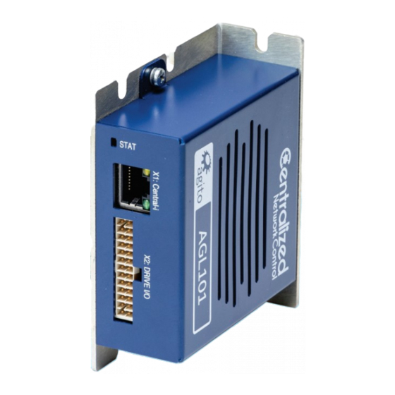
- Page 1 AGL10x Central-i Adapter Product Manual...
- Page 2 Agito Akribis Systems Ltd. Products Rights AGDx, AGCx, AGMx, AGAx, AGIx, and AGLx are products designed by Agito Akribis Systems Ltd. in Israel. Sales of the products are licensed to Akribis Systems Pte Ltd. under intercompany license agreement.
-
Page 3: Table Of Contents
Contents Product Description _____________________________________________________ 4 General Description ______________________________________________________________ 4 Part Numbering _________________________________________________________________ 5 System Design ___________________________________________________________________ 5 Technical Specifications ___________________________________________________________ 6 Environmental Specifications _______________________________________________________ 9 Safety _______________________________________________________________ 10 Safety Symbols _________________________________________________________________ 10 Safety Guidelines _______________________________________________________________ 10 Compliance ____________________________________________________________________ 11 Installation ___________________________________________________________ 12 Unpacking and Packing ___________________________________________________________ 12 Mounting _____________________________________________________________________ 12 3.2.1... -
Page 4: Product Description
General Description 1 Product Description General Description The AGL10x is a series of Central-i remote adapters to interface the Central-i network with third- party external devices, such as servo and stepper drives. The adapters provide two operations modes: Position closed loop: AGL10x converts Central-i current or velocity commands to analog ±10V ... -
Page 5: Part Numbering
Central-i remote fully featured adapter AGL101-CI-xx Central-i remote compact adapter AGL102-CI-xx Central-i communication CK: Connector Kit System Design AGL101 Agito or 3rd party non-Central-i servo or stepper drive Motor phases 9–36 VDC Encoder Optical Isolated I/Os Analog I/Os Differential I/Os... -
Page 6: Technical Specifications
Technical Specifications Technical Specifications Electrical/Mechanical Specifications Feature AGL101 AGL102 Number of axes Power supply 9–36 VDC 9–36 VDC Supported encoders 1 port; AqB or absolute BiSS-C 1 port; AqB Communication Central-i Central-i Isolated digital outputs – Non-isolated digital outputs (NPN up to 50 mA) Isolated digital inputs –... - Page 7 Technical Specifications I/O Specifications Feature Specification Power supply for optically isolated Voltage: 5–28 VDC I/Os Optically isolated digital inputs Type: PNP/NPN Propagation delay: 10 µs Max. frequency: 100 kHz Optically isolated digital outputs Type: PNP/NPN Max current: 0.5A (for NPN type), 0.3A (for PNP type) Propagation delay: 10 µs Max.
- Page 8 Technical Specifications Dimensions and Weight Feature AGL101 AGL102 Unit dimensions (max) H=89.5 mm, W=79.5 mm, D=18 mm H=45mm, W=73 mm, D=27 mm Package dimensions H= 96 mm x W=85mm x D= 23 mm H= 51 x W=69 x D= 33 Unit weight 250 g 150 g...
-
Page 9: Environmental Specifications
Environmental Specifications Environmental Specifications The operational range may be additionally limited by the internal temperature protection of the product. It is the user’s responsibility to avoid operating the product in environmental conditions that do not conform to the defined limits. Environmental Specifications Feature Specification... -
Page 10: Safety
Safety Symbols 2 Safety Safety Symbols Safety symbols indicate a potential for personal injury or equipment damage if the prescribed precautions and safe operating practices are not followed. The following safety symbols are used in the product documentation. Safety Symbols Symbol Meaning Description... -
Page 11: Compliance
Compliance Compliance Standards Compliance Description Standard Safety requirements – Electrical, thermal and energy IEC-61800-5-1 EMC requirements and specific test methods IEC-61800-3 This product is intended to operate in a machine or equivalent end-product. The machine or end- product must comply with any necessary safety standard as typically required for the same type of machine or end-product. -
Page 12: Installation
Unpacking and Packing 3 Installation Unpacking and Packing Save the original box and packing materials in case you need to pack and return the product to the manufacturer. To unpack the product: 1. Carefully remove the product from the box and the packing materials. 2. -
Page 13: Mounting Multiple Adapters
Mounting 3.2.2 Mounting Multiple Adapters When mounting multiple adapters within a cabinet, clearance between units must be at least 5 mm. In addition, top and bottom clearance must be at least 50 mm. Ambient temperature in the cabinet must not exceed limit defined in the section Environmental Specifications. -
Page 14: Electrical Installation
Electrical Installation Electrical Installation 3.3.1 Power Supplies The power sources provide power to the logic and I/O circuits. Power Source Description AGL101 AGL102 Logic power Supplies power to the logic and I/O circuits. 9–36 VDC 9–36 VDC Isolated I/Os power Supplies power to the optically isolated I/O 5–28 VDC 5 -28 VDC... - Page 15 Electrical Installation Ground bar AGM800 AGL101 AGL102 Agito or 3rd party non-Central-i servo or stepper drive Figure 7. System grounding Ground Domains The following table shows the ground domains in the AGL10x system: GND. Reference voltage for digital/analog circuits and signals.
-
Page 16: Communication - Central-I
Communication – Central-i It is critical to avoid ground loops in the system. A ground loop allows currents to return by two or more different paths, causing electromagnetic interference or even damage to wires. The system designer must carefully examine all GND connections in the system to ensure that no ... -
Page 17: Agl101 - Electrical Interfaces
AGL101 – Electrical Interfaces AGL101 – Electrical Interfaces 3.5.1 Interface X4: Power Connector X4 is used to supply 9–36 VDC to the AGL101. Figure 9. Power connector Connector X4: PWR Pin # Name Description VIN_EXTERNAL Power input: 9–36V, up to 1A continuous Ground –... -
Page 18: Interface X5: I/O Power
AGL101 – Electrical Interfaces 3.5.2 Interface X5: I/O Power Connector X5 supplies DC power supply to the isolated inputs and outputs. To use inputs and outputs, be sure to power up this port. Figure 10. I/O connector Connector X5: I/O PWR Pin # Name Description Isolated I/O power... -
Page 19: Interface X2: Drive I/Os
AGL101 – Electrical Interfaces 3.5.3 Interface X2: Drive I/Os Connector X2 is used for connecting external I/O devices to the adapter. For schematics and more information about these interfaces, refer to the section Electrical Interfaces Circuitry. Figure 11. Drive I/Os connector Connector X2: DRIVE I/O Pin # Name Software... - Page 20 AGL101 – Electrical Interfaces Software Pin # Name Description Representation Diff_Out_2- Differential input 2. Negative pin. Diff_Out_1- Differential input 1. Negative pin. A_Encoder_4- Differential input. Inverted. A_Encoder_3- Differential input. Inverted. A_Encoder_2- Differential input. Inverted. Ground. Analog_Output_1- Analog output 1. Inverted Analog_Input1_Return_1 Analog input 1 return.
-
Page 21: Interface X3: System I/Os
AGL101 – Electrical Interfaces 3.5.4 Interface X3: System I/Os Connectors X3 is used for connecting external I/O devices to the adapter. For schematics and more information about these interfaces, refer to the section Electrical Interfaces Circuitry. Figure 12. System I/Os connector Connector X3: SYSTEM I/O Pin # Name Software... - Page 22 AGL101 – Electrical Interfaces Software Pin # Name Description Representation Digital_Input_5 DInPort (bit 4) Isolated digital input 5. (NPN or PNP, depending on the connection of the group’s common pin). Digital_Input_3 DInPort (bit 2) Isolated digital input 3. (NPN or PNP, depending on the connection of the group’s common pin).
-
Page 23: Interface X1: Central-I
AGL101 – Electrical Interfaces 3.5.5 Interface X1: Central-i Connector X1 is used for communication between the adapter and the PC. Figure 13. Communication connector (Central-i) Connector X1: Central-i (RJ45) Pin # Name Description DATA_0+ Data channel 0+ DATA_0- Data channel 0- DATA_1+ Data channel 1+ DATA_2-... -
Page 24: Agl102 - Electrical Interfaces
AGL102 – Electrical Interfaces AGL102 – Electrical Interfaces 3.6.1 Interface X1: Power Connector X1 is used to supply power to the entire unit. The input voltage is directly connected to the adapter power bridge to generate the internal logic power that powers the adapter. The adapter includes protection to prevent damage if polarity is inverted at the power input. -
Page 25: Interface X3: Drive I/Os
AGL102 – Electrical Interfaces 3.6.2 Interface X3: Drive I/Os Connector X3 is used for connecting external I/O devices to the adapter. This port can be used for connection between the adapter and other external drivers. For schematics and more information about these interfaces, refer to the section Electrical Interfaces Circuitry. - Page 26 AGL102 – Electrical Interfaces Software Pin # Name Description Representation Digital_Output_4 DOutPort.bit(3) Non-isolated digital output 4. NPN. Digital_Output_2 DOutPort.bit(1) Non-isolated digital output 2. NPN. Digital_Input_4 DInPort.bit(1) Non-isolated digital input 2. NPN. Digital_Input_2 DInPort.bit(3) Non-isolated digital input 4. NPN. Common ground Not connected Common ground Connector manufacturer...
-
Page 27: Interface X4: I/O (Inputs For Limit Switches)
AGL102 – Electrical Interfaces 3.6.3 Interface X4: I/O (Inputs for Limit Switches) Note – This port is used for the connection of the limit switches Figure 16. Drive I/O Connector Connector X4: I/O Pin # Name Software Description Representation VIN_RTN Common ground (X1 pin2) Output power supply. -
Page 28: Interface X2: Central-I
AGL102 – Electrical Interfaces 3.6.4 Interface X2: Central-i Connector X2 is used for communication with the Central-i master controller, such as the AGM800, and other remote adapters and devices. X2 is used for communication between the adapter board and other Central-i serial devices. Figure 17. -
Page 29: Electrical Interfaces Circuitry
Electrical Interfaces Circuitry Electrical Interfaces Circuitry 3.7.1 Isolated Digital Inputs – AGL101 Note – AGL102 does not support isolated digital inputs. Figure 18. Isolated digital inputs – AGL101 Isolated digital inputs are organized as groups with a dedicated common pin. This enables ... -
Page 30: Isolated Digital Outputs - Agl101
Electrical Interfaces Circuitry 3.7.3 Isolated Digital Outputs – AGL101 Note – AGL102 does not support isolated digital outputs. Figure 20. Isolated digital outputs – AGL101 The digital output interface circuit in AGL101 is identical for isolated digital outputs 1, 2 and 3. ... -
Page 31: Non-Isolated Digital Outputs
Electrical Interfaces Circuitry 3.7.4 Non-Isolated Digital Outputs Figure 21. Non-isolated digital outputs The digital output is NPN only. The digital output current is limited to 50 mA. The outputs are designed for resistive loads. For inductive loads, an external flyback diode is ... -
Page 32: Analog Outputs
Electrical Interfaces Circuitry 3.7.6 Analog Outputs Figure 23. Analog Outputs The electrical interfaces of all analog outputs are identical. The analog output range is from -12V to +12V, with resolution of 16 bits. Output resistance is 10 Ω ... -
Page 33: Differential Outputs
Electrical Interfaces Circuitry 3.7.8 Differential Outputs Figure 25. Differential outputs Differential outputs use two complementary signals (Differential_Output+ and Differential_Output-) to receive information. The same electrical signal is sent as a differential pair, each in its own conductor. The pair is wired ...
Need help?
Do you have a question about the AGL10 Series and is the answer not in the manual?
Questions and answers