Table of Contents
Advertisement
Quick Links
Vorwort
Dieses Handbuch wurde in zwei Sprachen verfaßt. Um Ih-
nen die Handhabung zu erleichtern, ist der deutschsprachi-
ge Teil mit einem dunkelgrauen Balken und der englisch-
sprachige durch einen hellgrauen Balken gekennzeichnet.
Preface
This manual has been written in English and in German. In
order to differentiate between the two languages quickly, the
German section has a dark grey bar and the English section
has a light grey bar.
1
Advertisement
Table of Contents

Summary of Contents for PANELWARE MAPWP150-0E
- Page 1 Vorwort Preface Dieses Handbuch wurde in zwei Sprachen verfaßt. Um Ih- This manual has been written in English and in German. In nen die Handhabung zu erleichtern, ist der deutschsprachi- order to differentiate between the two languages quickly, the ge Teil mit einem dunkelgrauen Balken und der englisch- German section has a dark grey bar and the English section sprachige durch einen hellgrauen Balken gekennzeichnet.
- Page 2 Inhaltliche Änderungen dieses Handbuches behalten wir uns The information contained herein is believed to be accurate ohne Ankündigung vor. Die Bernecker und Rainer Industrie- as of the date of publication, however, Bernecker und Rai- Elektronik Ges.m.b.H. haftet nicht für technische oder druck- ner Industrie-Elektronik Ges.m.b.H.
- Page 3 PANELWARE P150 USER'S MANUAL Version: 1.0 (May 1997) Model No.: MAPWP150-0E ® Windows is a registered trademark of the Microsoft Corp. ® MS-DOS is a registered trademark of the Microsoft Corp.
-
Page 5: Table Of Contents
Table of Contents Preface ......................................1 1 General Information ................................55 1.1 Measurements ................................56 2 Technical Data ..................................57 3 Installation ....................................58 4 Component Overview ................................60 5 Component Description ................................. 61 5.1 LCD Display .................................. 61 5.2 Matrix Keypad ................................62 5.3 Controller .................................. - Page 6 5.3.7 Lithium Battery ..............................70 5.3.8 FlashPROM ................................. 71 6 Connection P150 - PLC ................................. 72 6.1 Cabling Schematics ..............................73 7 Connection P150 - PC ................................76 7.1 Cabling Schematic ............................... 77 8 Connection P150 - Printer ..............................78 8.1 Cabling Schematic ...............................
-
Page 7: General Information
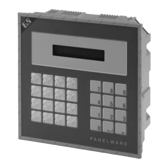
1 General Information The P150 MMI is a powerful and space saving operator panel. It can be programmed using the PANELWARE Con- figuration Software (PCS). The P150 MMI functions as an intelligent panel controller. It is equipped with a 2 x 20 LCD display, 16 key matrix keypad with key illumination and a 12 key numerical keypad. -
Page 8: Measurements
1.1 Measurements NOTE: For the most part, measurements are given as metric values in this manual. There are metric to imperial conversion tables provided in the last section of the English version of this document. -
Page 9: Technical Data
Matrix Keypads Matrix Keypad 16 keys (incl. LEDs) Numerical Matrix Keypad 12 keys Controller Programmed using PANELWARE software Supply Voltage 24 VDC (min. 18 VDC, max 30 VDC) Interfaces RS232 programming interface (not electrically isolated) RS232 interface (not electrically isolated) -
Page 10: Installation
3 Installation 1) Insert mounting pins onto P150 panel. 2) Apply sealant to lip of P150 panel. - Page 11 3) The cutout measurements are 188 x 188 mm. Place the P150 in panel cutout so that the lip of the unit face 4) Install spring clips onto back of P150 panel in order to is pressed against edge of the cutout. hold it in place.
-
Page 12: Component Overview
4 Component Overview 1 Battery 2 Contrast Setting 3 Power Connection 4 Programming Interface (RS232) 5 Reset Button 6 Mode Number Dial 7 RS232 Interface 8 RS422/485 Interface... -
Page 13: Component Description
5 Component Description 5.1 LCD Display The P150 is equipped with a 2 x 20 LCD display. This display is back-lit (black on yellow). A contrast setting is available on the back of the unit. The characters are 5 mm high. -
Page 14: Matrix Keypad
5.2 Matrix Keypad The P150 has two matrix keypads. The keypad on the left has 16 short-stroke keys with LED indication. The keypad on the right is a numerical keypad with 12 short-stroke keys labelled with 0 to 9, enter and clear. -
Page 15: Controller
The controller section of the P150 is equipped with a power connection, three interfaces, backup battery, mode switch, Reset button, LED indicators and a contrast setting potentiometer. The controller is programmed using PANELWARE Con- figuration Software (PCS). Downloading programs and updating the operating system is described in detail in "Software". -
Page 16: Interfaces
5.3.2 Interfaces RS232 Programming Interface IF0 9 Pin D-Type Connector (M) RS232 +5 V... - Page 17 RS232 Interface IF1 9 Pin D-Type Connector (M) RS232 12 V...
- Page 18 RS422/485 Interface IF2 9 Pin D-Type Connector (F) RS422 RS485 SHIELD SHIELD DATA +5 V +5 V DATA Interfaces IF1 and IF2 are basically only one interface. However, it is routed through a male and female connector because of the different interface types. All interfaces are equipped with two LEDs which indicate if data is being transmitted or received (see "LEDs").
-
Page 19: Leds
5.3.3 LEDs The P150 MMI is equipped with a RUN LED, a HALT LED and interface LEDs. -
Page 20: Mode Switch Number Dial
5.3.4 Mode Switch Number Dial The number dial is used to set the operating mode for the controller. Different operating modes can be activated by setting the mode switch number dial to one of the following numbers. These operating modes affect how the unit behaves after a power-on. -
Page 21: Reset Button
5.3.5 Reset Button A hardware reset can be executed with this button. Different functions can be expected depending on the number set on the mode switch number dial (see description for mode switch number dial). 5.3.6 Contrast Setting The contrast of the LCD display can be adjusted using a dial on the back of the unit (see "Component Overview"). -
Page 22: Lithium Battery
5.3.7 Lithium Battery The lP150 is equipped with a 3V/950mAh lithium battery for buffering data. It can be removed from the battery compartment by pulling the removal strip and then replaced with a new one (made sure the new batter y is inserted over the removal strip). Replacement batteries can be ordered from B&R (see "Accessories"). -
Page 23: Flashprom
5.3.8 FlashPROM The panel controller has non-volatile memory in the form of an FlashPROM. The FlashPROM is split into two separate areas (Banks). System Bank contains the operating system, which is necessary to process the panel program created by the user. The system bank cannot be deleted by the user. -
Page 24: Connection P150 Plc
6 Connection P150 The P150 MMI can be connected to a PLC via the RS232 or RS422/485 interface (see cable schematics on following pages). P150... -
Page 25: Cabling Schematics
6.1 Cabling Schematics RS232 Interface The serial cable used to for the connection to between the P150 and PC, which can be ordered from B&R, can also be used to connect the P150 to a PLC (model number: 0G0001.00-090). Note: If you make this cable yourself, the jumpers shown above are not required. - Page 26 RS422/485 IF2 is a combination RS422/485 interface. RS422...
- Page 27 RS485 NOTE: The first and last node on the RS485 network must be equipped with a termination resistance. Resistor Values R1 - 390 Ω R2 - 150 Ω R3 - 390 Ω...
-
Page 28: Connection P150 Pc
7 Connection P150 The P150 MMI is connected with the PC via a serial interface. Interface IF0 on the panel is connected to an RS232 interface on the PC (COM1 or COM2) using a serial cable which can be ordered from B&R (model number: 0G0001.00-090). P150... -
Page 29: Cabling Schematic
7.1 Cabling Schematic The serial cable used to connect the P150 to a PC can be ordered from B&R (model number: 0G0001.00-090). NOTE: An adapter is necessary if the 25 pin connector is used on the PC instead of the 9 pin D-type male serial interface. -
Page 30: Connection P150 Printer
8 Connection P150 Printer A printer can be connected to the IF0 or IF1 serial interface on the P150 MMI. The printer must have an RS232 interface. Printer P150 Interface Selection The interface and baudrate which should be used on the MMI are selected using PCS. -
Page 31: Cabling Schematic
8.1 Cabling Schematic The serial printer cable can be connected to the IF0 or the IF1 interface on the panel controller:... -
Page 32: Software
The P150 is an intelligent operator panel. All visualization and keypad functions are managed by the P150 operator panel. A program is created on a PC using PCS (PANELWARE Configuration Software) and then transferred to the operator panel. This program can also handle data exchange between the PLC and the operator panel (data is written to or read from the PLC). - Page 33 Load Panel Program 1. Make the connection between the PC and P150 MMI (IF0). A serial cable is used to make this connection. 2. The panel program can either be downloaded in Teach Mode or Run Mode starting with PCS V2.1. Teach Mode - Download and run panel program, panel remains in Run Mode after a reset and goes into Teach Mode after a power-on...
-
Page 34: P150 Operating System Update
9.2 P150 Operating System Update An operating system update can be made using the PANELWARE Configuration Software (PCS). To update the operating system, you have to switch to Bootstrap Mode (see "Mode Switch Number Dial" section in this manual). Update Operating System 1. -
Page 35: Error Messages
10 Error Messages In order to test the P150 MMI, the 24 V supply must be connected. The following message is displayed for a shor t time. Start 0..1..01234567890123456789 String <DC2> Version: x.y <DC4> String <DC2> Status: abccdefgh <DC4> hexadec. - Page 36 The P150 MMI tries to start a panel program after a power-up (or reset). If no panel program exists, the “No program” error message appears on the screen. Transfer a panel program from the PC (PCS). See the following manuals: PANELWARE Software User’s Manual (model number: MAPWSW-E) and PANELWARE Application Manual (B&R Drivers) (model number: MAPWBR-E) .
-
Page 37: Other Errors
11 Other Errors Display is dark Is power applied? Display is illuminated, but no text is seen Download operating system. Download project. Restart P150 MMI. LEDs do not light on the Keys After power-on (or a reset) the LEDs on the keypad must light for a short period of time. Unit must be replaced. - Page 38 Cannot make connection with PC The P150 MMI must be connected to the PC, on which the PCS program (PANELWARE Configuration Software) is installed, via interface IF0. If a panel program cannot be transferred to or from the panel, the following points should be checked:...
-
Page 39: Accessories
12 Accessories Accessory Amount Accessory Set Terminal Block (4 pin) Lithium Battery Label Sheets The accessories listed are included with the P150 MMI delivery. - Page 40 Accessory Set Contents of Accessory Set: Letter Description Amount Mounting pin set Tube of sealant Spring clips A PANELWARE assembly/installation guide and a safety data sheetis also included with the P150 MMI delivery.
- Page 41 Terminal Block (4 pin) Terminal block for supply voltage on the P150 MMI. See "Voltage Supply" section in this manual for additional information.
- Page 42 Lithium Battery Lithium Battery for the P150 MMI. Replacements can be ordered from B&R in sets of 5 (model number: 0A201.9). See "Lithium Battery" section for information on installing or exchanging the lithium battery.
- Page 43 Label Sheets Labels for keypads: 1 Label sheet for 16 key modules (A4 size) 1 Label sheet for 16 key modules (US Letter size) Every sheet of labels consists of 6 module legend layouts for the respective keypad. These sheets are perforated for quick and easy access to new labels.
-
Page 44: Conversion Tables
13 Conversion Tables Metric and English Equivalents Some the values in this manual are only given as metric values. The following formulas and charts are given to help with any conversion problems that you may have. Temperature Below are two formulas to help in the conversion from Fahrenheit to Centigrade and vice versa. Linear Measure &... - Page 45 ° ° ° ° 5/9 x (°F - 32) = °C (9/5 x °C) + 32 = °F...
-
Page 47: Index
Index... - Page 49 Index Contrast Setting ............ 69 Controller ............... 63 Conversion Tables ..........92 Accessories ............87 Accessory Set ..........88 Label Sheets ........... 91 Lithium Battery ..........90 Terminal Block ..........89 Error Messages ..........83, 85 Beschriftungsblätter ..........91 FlashPROM ............71 Components ............
- Page 50 Installation ............. 58 Reset Button ............69 Interfaces ............... 64 RS232 Programming Interface IF0 ..64, 65, 66 RS232 ............64, 65 RS422 ............. 66 RS485 ............. 66 Software ..............80 Loading Projects ..........80 Operating System ........... 82 LCD Display ............61 Starting Projects ..........
- Page 51 Zubehör für PANELWARE-Tableaus Beschriftungsblätter ........91 Lithium-Batterie ..........90...
Need help?
Do you have a question about the MAPWP150-0E and is the answer not in the manual?
Questions and answers