
Related Manuals for Rugged Computing ATLAS slim 14

Summary of Contents for Rugged Computing ATLAS slim 14
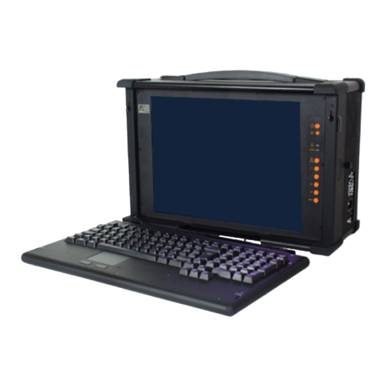
- Page 1 Rugged Industrial Portable Computer System Assembly Manual A Technical Manual for System Integrators and Service Technicians...
- Page 2 The information contained in this document is believed to be accurate. However, no responsibility is assumed for its use, nor for any infringements of patents or other rights of third parties which may result from its use. This information is subject to change without notice.
-
Page 3: Table Of Contents
CONTENTS Getting Started………………………………………………………………………………..4 Before you Start………………………………………………………………………………..5 Precautions……………………………………………………………………………………..6 Power Connections…………………………………………………………………………..6 Ventilation……………………………………………………………………………………..6 Care for the LCD……………………………………………………………………………...6 Tools and Supplies Needed………………………………………………………………...…7 Subassembly Contents…………………………………………………………………………7 Parts Contents…………………………………………………………………………………..7 Identifying Parts and Controls…………………………………………………………………8 Opening the Side Access Covers……………………………………………………………8 Removing Side Covers…………………………………………………..……………………..8 Slim Model Side Views…….. …………………………………...……………………………..8 Front View………………………………………………………………………………..…….10 Detaching the Keyboard………………………………………………………………………11 Opening the Chassis……………………………………………………………………...…12 Removing the Back Cover……………………………………………………………………13... - Page 4 Installing the interface card……………………………………………………………….24 Installing the interface card Support……………….…………………………………….25 Installing the Power Supplier And All Cables From CPU card……………………………27 Installing the Drive Assembly…………………………………………………………………29 Installing Parallel and Serial connector……………………………………...………………33 Keep Cleanness Area to prevent conflict with back Fan………………………….……34 Cover the Back case…………………………………………………………………….……35 Using the System Controls………………………………………………………………..36 Starting your System…………………………………………………………………………37 OSD Controls…………………………………………………………………………………37...
-
Page 5: Getting Started
1. Getting Started Before you Start………………………………………………………………………………..5 Precautions………………………………………………………………………………………6 Power Connections……………………………………………………………………………6 Ventilation…………………………………………………………………………………...….6 Care for the LCD………………………………………………………………………………6 Tools and Supplies Needed……………………………………………………………………7 Subassembly Contents…………………………………………………………………………7 Parts Contents…………………………………………………………………………………7 Identifying Parts and Controls…………………………………………………………………8 Opening the Side Access Covers……………………………………………………………8 Removing Side Covers………………………………………………………………………8 Side View…………………………………………………………………………………….…10 Front View……………………………………………………………………………………...11 Detaching the Keyboard………………………………………………………………………11... -
Page 6: Before You Start
Before You Start The major component of the subassembly is the chassis. The chassis comes pre- assembled with: • An Active Matrix LCD • LCD Controller • An PICMG backplane board with 2 PCI slots ( one 338mmX 118 , one half size 175mm X 118) or 1 ISA((Max length 338 X 118mm) -
Page 7: Precautions
Precautions Power Connections Use the Supplied Power Cord The subassembly is shipped with a power cord compatible with the AC wall outlet in your region. Power Supply Type Before plugging in the power cord, examine your power supply to see if you have an autosensing or non-autosensing power supply. -
Page 8: Tools And Supplies Needed
Tools and Supplies Needed Before beginning your work, make sure you have the following tools and supplies available: • A #2 Phillips (cross head) screwdriver. • An anti-static wrist strap (recommended). Subassembly Contents The subassembly consists of: • This subassembly guide. •... -
Page 9: Identifying Parts And Controls
Identifying Parts and Controls Opening the Side Access Covers The side access covers provide side impact protection for the I/O ports and drive bays. The access covers must be opened to access I/O connectors. Turn the thumbscrew in the counter-clockwise direction to open the access covers. - Page 10 Use the photos below to identify the components and I/O ports that are accessible from the two sides of the chassis. The illustration shows the external connectors and components of a completely assembled system. Your subassembly has only knockout holes instead. On the left side of the chassis you will find the following: 1.
-
Page 11: Front View
You access the front panel controls by first disengaging the keyboard. Disengage the keyboard from the chassis latches by sliding the latch tabs on both sides of the chassis upwards as shown, and simultaneously pulling the top part of the keyboard away from the chassis. -
Page 12: Detaching The Keyboard
Detaching the Keyboard The keyboard is normally hinged to the chassis via two latch bolts located on the top of the keyboard. You can detach the keyboard by sliding both release pegs towards each other and compressing the latch bolts until they slide out of the slots. -
Page 13: Opening The Chassis
2. Opening the Chassis Removing the Back Cover……………………………………………………………………13 Identifying the Internal Parts………………………………………………………………..14 Removing the Drive Carriers…………………………………………………………………14 Removing the Power Supply…………………………………………………………………16 Removing the PICMG backplane board…….…………………………………………17 Removing the Slot Positioner metal bracket……………………………………………18... -
Page 14: Removing The Back Cover
Removing the Back Cover You must first remove the back cover to work on the interior of the chassis. Please observe the following safety guidelines when removing the back covers: • Always power down the system. • Always turn off any peripheral device connected to the system. •... -
Page 15: Identifying The Internal Parts
Identifying the Internal Parts 1. Power Supply 2. PICMG backplane 3. Drive Bay Carrier Remove everything inside the case Before install the PICMG CPU card or and expansion card, all the parts inside the case have to be removed, There are following main parts need to be move out: 1. - Page 16 There are also have 2 screws along the left side of case(if LCD face to you) that secures it to the chassis as shown at right picture. Once you have removed all 4 screws, you can now remove the Driver Carrier from the chassis. #3 screw (refer to page.
-
Page 17: Removing The Power Supply
B. Removing the Power Supply There are have 2 screws along the right side of case(if LCD face to you) that secures the power supplier to the chassis as shown at left picture. #6 screw (refer to page. 7) There are also have 2 screws along the bottom side of case that secures the power supplier to the chassis as shown at left picture. -
Page 18: Removing The Picmg Backplane Board
C. Removing the PICMG backplane board There is a PICMG backplane board which already on a metal Carrier. You need to remove the Carrier out by unscrew all the 6 screws as following picture. But keep the PICMG board mounted on the metal Carrier. #5 screw (refer to page. -
Page 19: Removing The Slot Positioner Metal Bracket
D. Removing the Slot Positioner metal bracket The Slot Positioner metal bracket as shown at left picture which is used to screw the CPU card and all expansion cards. This metal bracket need to be removed before install the PICMG board. To remove this bracket , check with left picture There are 4 screws at the left side of the case And 1 screw inside the case need to be removed... -
Page 20: Assemble The System
3. Assemble the System The normal procedure for Installing as complete system should follow following steps A. Installing the PICMG and CPU card B. Installing CPU card with the PICMG backplane into the case C. Installing the CPU card stablizer D. -
Page 21: Installing Cpu Card With The Picmg Backplane Into The Case
B. Installing CPU card with the PICMG backplane module To install the module into the case, keep in mild there is a plastic cpu card holder as shown in following picture. The cpu card edge should slide into the card holder as shown at left picture, do not left the cpu card dangling as right side picture. - Page 22 After the module is install inside the chasis, the Slot Positioner metal bracket also need to be screwed to the chasis, there are 5 screws1- 4 at left side of the case (use M3X8 screw) and 1 inside the case (use M3X4 screw) as shown at below left picture.
-
Page 23: Installing The Cpu Card Stabilizer
C. Installing CPU card stabilizer If your cpu card is long enough , then you need to hold the cpu card end with the card stabilizer which is shown as following picture. Before screw down the stabilizer, shift the stabilizer all the way right then screw down.use screw #5 (refer to page. - Page 24 The arrangement of the cable should be like following picture. This arrangement may different from the CPU card connector, please refer the CPU card docum ent from your u card vendor, and check with the ATX Power Enable signal arrangement. Then arrange the pin arrangement of cable so to make it same as the picture shown at below.
-
Page 25: Installing The Interface Card
E. Installing Interface Card Before install the interface card into the case, screw the interface card with a expansion part for the interface card to screw to the case. See following picture, at right hand side there is a small piece of expansion part, screw it with the interface card as shown in the picture. -
Page 26: Installing The Interface Card Support
The interface card need to screw to the case as shown at following picture. #7 screw (refer to page. 7) F.Installing Interface Card Support ll the interface card need to be supported by a Support parts, otherwise the interface card will be easily fall down. The Support is a piece of plastic with slide as shown at pa # 12 in following picture. - Page 27 Put the Support as following picture. If the part is too wide to use then you should cut it to fit you requirement. Also there are two screws hole for your convenience to choice. Then adjust the Support, using part #13-Hexagon Screw Driver to adjust the screws at case bottom (see picture at below) which will move the Support up or down to support the interface card.
-
Page 28: Installing The Power Supplier And All Cables From Cpu Card
G. Installing Power Supplier And All Cables From CPU card onnect all the power cord with the u card and all necessary cable nnection (Fans, and one special ble to LCD screen as next picture) and install the Power supplier as left picture. - Page 29 There are 4 screws need to screw for the Power Supplier, 2 screws(#6 screw refer to page. 7) are locate at the right side o f the case and 2 are locate at the bottom of the case(1-2 or 2-3) shown as following picture.
-
Page 30: Installing The Drive Assembly
. Installing Hard Drive , FDD and CD Drives he Drive Carrier is designed to support 3.5” FDD drive, 1 Hard Drive and 1 Slim Type D-ROM drive. a. Install the FDD drive with 4 screws as following picture(Using M2.6X3screw) (#8 screw refer to page. - Page 32 c. Install the HDD drive with 4 screws as following picture . Install the FDD cable adapter board as following picture, the FDD flex cable also need to be connected now.
- Page 33 d. Before install the Diver Carrier Module into the case, connect all the necessary cables from cpu card(power cable, IDE cable and FDD cable, Parallel port cable, Serial port cable) first. After the module is installed it will cover the cpu card. Then install the Drive module, follow the picture as below, first move the module down to let the whole Carrier goes into the case, after it goes into the case move the Module slightly up as Arrow-2 then complete it as Arrow-3.
-
Page 34: Installing Parallel And Serial Connector
Installing Parallel and Serial Connector here are a metal panel for 4 Serial port outlet and 1 Parallel port outlet, connect all the erial and parallel cable with cpu card (these cable should already connected to the cpu oard before the Drive Carrier is installed)and mount to this metal panel first. -
Page 35: Keep Cleanness Area To Prevent Conflict With Back Fan
Then mount this I/O panel to the Driver Carrier with 2 screws as below picture. There re 2 higher boss at the Driver Carrier which is used to mount this I/O panel. J. Keep Cleanness Area to prevent conflict with back Fan The circle area at below picture need to be keep clean from any cable go around that area, any cable there will be possible touch the back fan and cause an unpleasant noise. -
Page 36: Cover The Back Case
K. Cover the Back case efore cover the back case the back case Fan need to connect to Power supplier as elow... -
Page 37: Using The System Controls
. Using the System Controls Starting your System…………………………………………………………………………37 SD Controls…………………………………………………………………………………37 djusting the OSD Parameters………………………………………………………………38... -
Page 38: Starting Your System
Starting your System Before starting your system, plug in the power cord and make sure the video and input device connectors are plugged in. Release the keyboard latches and lay the keyboard flat on your work area. Power up your system by pressing the power switch push button located on the front panel of your chassis. -
Page 39: Adjusting The Osd Parameters
Adjusting the OSD Parameters ou can use the buttons located on the front panel to enter and access the OSD. Main M enu: Auto-Adjustment – The AD Card auto adjusts all the parameters for your LCD. Contrast Menu Auto-Balance – Automatically sets the balance and contrast for your LCD. -
Page 40: Appendix
5. Appendix Specifications…………………………………………………………………………………40 General Features……………………………………………………………………………40 Display Selection…………… ………………………………………………………………40 Environment…………………………………………………………………………………40 imen ions & Weight…………………………………………… …………………………40 Troubleshooting Techniques……………………………… …………………………………41... -
Page 41: Specifications
Specifications General Features • Support 2 slot ( one 338mmX 118 , one half size 175mm X 118) ISA(338 X 118mm) • Supports PII-P4 type processors. • All aluminum constructed chassis with anode process • Rubber bumper protected corners. • Dual point add-on card retention system. •... -
Page 42: Troubleshooting Techniques
Troubleshooting Techniques No Screen after pressing the fr ont power switch: Power supply fan not spin ning: • Check power source • Check power cord connection. • Check if all power connectors inside the chassis have been properly connected. • Check main power switch on power supply . - Page 43 CD screen shows garbage or bad characters or vertical/horizontal color lines or bars: • Detach the video connection to the LCD screen and attach it to a good external CRT monitor. If the external CRT monitor shows normal video then it could be a com patibi lity issue.
Need help?
Do you have a question about the ATLAS slim 14 and is the answer not in the manual?
Questions and answers