Table of Contents
Advertisement
Quick Links
Advertisement
Table of Contents

Summary of Contents for Segen Solar EPM Plus 5G
- Page 1 Application Note – Solis and EPM Quick Setup Guide...
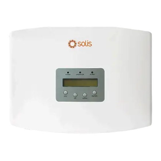
- Page 2 Product Description Front View EPM Plus 5G Front View EPM Plus 5G The Solis EPM 5G is a device that allows you to adjust export values to satisfy local network regulatory requirements. General Notes • Do not place communication cables with DC and AC cables in the same conduits or trunking as this may influence the normal communications.
- Page 3 System Connection Wiring Diagram The wiring diagram is also found in the user manual and EPM quick installation guide. This application note must be used in conjunction with the user manual for any further reference. Communication The EPM and Inverter communicates with Modbus protocol via RS485 2 wire. UTP/FTP Twisted pair cable should always be used.
- Page 4 EPM Settings Once the EPM is wired correctly and powered on, the unit needs to be configured. On power on the default screen displays your active power (+ means consuming, – means exporting may mean the CTs have been reversely installed if power is supposed to be consumed). Note this is the overall power and it is important to ensure that the CTs are checked for correct polarity on the individual phases.
- Page 5 Setting: Backflow Power This value shows the maximum power that can be pushed back into the local grid. Export values must be checked with the local municipalities and must be followed. Note that only surplus power is exported i.e. if solar generation is more than consumption and if surplus power exceeds max export value, the generation will be throttled to the set value.
- Page 6 Setting 3: Set Meter CT The CT ratio is set according to the installed CTs. Because all the CTs used for the EPM must have a secondary 5A current, the ratio is obtained by dividing the Primary Current/Secondary Current e.g., a 200:5 CT will be 0040:1 Setting: FailSafe Must be set to run.
- Page 7 Setting: Backflow Work Mode Mode 2 is always recommended for unbalanced loads. (for detailed explanation refer to the user manual. After adjusting the settings successfully, check on the advanced info menu option for the following. Inverter Power: This will display the power of each inverter as measured by the EPM CT Connect Status: This must show OK, otherwise if CT_NG is displayed it means that the CT is open circuit or current passing through is extremely low which is usually a result of using CTs with a secondary current less than the recommended 5A.
- Page 8 SolisCloud Monitoring After successful setup of the EPM and inverter settings, please refer to the SolisCloud Operation Manual for Organization User for details on how to connect the plant to the internet for remote monitoring and creating an account for cloud monitoring. NB: Remote monitoring data is not real time;...
Need help?
Do you have a question about the EPM Plus 5G and is the answer not in the manual?
Questions and answers