Table of Contents
Advertisement
Quick Links
DC58 & DC58M Installation &
DC58 & DC58M Installation &
Programming Guide Overview
Programming Guide Overview
General
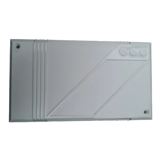
The DC58/58M digital communicator consists of a
single PCB fitted in a small polycarbonate case. It is
used to transfer status information from an alarm
system to a dedicated Alarm Receiving Centre (ARC)
via the Public Switched Telephone Network (PSTN). The
DC58M offers the same features as the DC58 but it also
functions as a V21 modem. The DC58M is required
when using the up/downloading feature on
compatible Menvier Security control panels.
Operating Modes
The D C5 8 ca n be u sed a s a s t a n d - a lon e
communicator, in this mode the communicator is
hard-wired to the control panel using the appropriate
terminal block connections. Alternatively the unit can
be plugged on to a suitable Menvier Security control
panel, such as the TS510, TS700, TS790, TS900, TS2500
or TS2200. When used in this mode the communicator
Plug-on Mode
Plug-on to
Menvier Security
control panels
Stand-alone Mode
(DC58 Only)
Terminal
connections for
other control
panels
Figure 1. Operating Modes
plugs on to the control panel using the lead supplied.
The DC58M can only be used in the plug-on mode.
NVM Programming
All programmed data is stored in a plug-in NVM
(Non-Volatile Memory) which will be retained for up to
five years with no power present. The NVM can be
496545 Issue A
programmed by using a Menvier Security LCD Remote
Keypad (P/No. NETLCD) and an engineer's interface
lead (P/No. NETEKI) which will plug directly on to the
DC58/58M. Alternatively the NVM can be programmed
using the desktop programmer PP5.
Your ARC will normally provide a programming service
and will supply a pre-programmed NVM on request.
Technical Specifications
Supply:
Low Battery:
Outputs:
Ch 1 - 8:
NETLCD Remote Keypad
(Programmer)
Modem:
Programmer:
Case Size:
NETLCD Remote Keypad
Weight
(Programmer)
REN value:
BT Approval:
Series Voltage Drop
The voltage drop introduced by the series connection
through the DC58/58M at a line current of 40mA is 0.1V.
When used with other apparatus (telephone, fax etc.)
the total voltage drop @40mA MUST NOT exceed 2.0V.
1 of 8
DC58 & DC58M
11.5V - 14V; 35mA dc (Standby);
100mA dc (Active)
The installer must ensure that
power drawn by the DC58/58M
plus any other auxiliary apparatus is
within the rating of the control
panel (host) power supply.
Detection threshold is at 10.8V +/-
0.2V
[1+]: Switched +ve @100mA
[2-]: Switched -ve @100mA
Maximum input voltage 28V.
Channel input trigger either +ve or
-ve applied (JP3)
300 Baud (V21)
NETLCD remote keypad & NETEKI or
PP5.
142(w) x 82(h) x 36(d) mm.
265g
0.0
DC58 - S/1100/3/R/503310
DC58M - S/1100/3/R/503311
DC58 & DC58M
Advertisement
Table of Contents

Summary of Contents for Menvier DC58
- Page 1 Alarm Receiving Centre (ARC) and will supply a pre-programmed NVM on request. via the Public Switched Telephone Network (PSTN). The DC58M offers the same features as the DC58 but it also functions as a V21 modem. The DC58M is required Technical Specifications when using the up/downloading feature on compatible Menvier Security control panels.
-
Page 2: Installation
TS900 TO CONTROL REMOTE PANEL TS900 REMOTE A1 B Figure 2. DC58 PCB Layout Figure 3. DC58M PCB Layout Test Call Output 2- (SELV) Short these two pins to initiate a test call. Programmable switched -ve output rated @100mA. Removable Non-Volatile Memory used to store all Output 1+ (SELV) programmed data. -
Page 3: Plug-On Installation
Do not attempt to continue if the mains or battery supply is still present. Remove the cover from the DC58/58M case and if Cable Entry appropriate fit a pre-programmed NVM. Connect the interface lead to the control panel... - Page 4 +ve. RS Components (Part No. 470-487). Connect power to the control panel. If the DC58 is Replace the bottom section of the master jack b e i n g u s e d a s a s t a n d - a l o n e , w a i t f o r socket and do up the two screws.
-
Page 5: Programming Menu
DC58 & DC58M Programming Programming Menu Digi Output 2 is DC58 Version 2.2 SET/DAY CHANNELS Line Fault Press Any Key * * * 4 * * * * Press any key Select output type: Select Set/Day (Open/Close) channels by pressing [1] - [8]... -
Page 6: Point Id Extended Format
DC58 & DC58M Point ID Extended Format Ring Count (DC58M Only) When the DC58/58M is used in the "plug-on mode" (i.e. The DC58M Ring Count can be programmed for one connected to a Menvier Security control panel) it is of the following options:... -
Page 7: Monitor Mode
When the NETLCD remote keypad is left plugged on to When the "TEST CALL" pins are momentarily shorted the the DC58/58M it will act as a monitor, so that during DC58/58M will send a test call to all programmed testing to the ARC the display will show the telephone numbers. - Page 8 DC58 & DC58M This page intentionally left blank 8 of 8 DC58 & DC58M 496545 Issue A...
Need help?
Do you have a question about the DC58 and is the answer not in the manual?
Questions and answers