Table of Contents
Advertisement
PORTABLE
FORCED AIR DIESEL HEATERS
"USER'S MANUAL"
MODEL : IH75000, IH125000, IH170000
Before the first use of this heater, please read this USER'S MANUAL
very carefully. This USER'S MANUAL has been designed to instruct
you as to the proper manner in which to assemble, maintain, store, and
most importantly, how to operate the heater in a safe and efficient manner.
Please keep this manual for future reference.
Distributed by: Companion Brands, Bundoora VIC 3083
www.companionbrands.com.au
Advertisement
Table of Contents

Subscribe to Our Youtube Channel
Related Manuals for PASECO IH75000


Summary of Contents for PASECO IH75000
- Page 1 PORTABLE FORCED AIR DIESEL HEATERS “USER’S MANUAL” MODEL : IH75000, IH125000, IH170000 Before the first use of this heater, please read this USER’S MANUAL very carefully. This USER’S MANUAL has been designed to instruct you as to the proper manner in which to assemble, maintain, store, and most importantly, how to operate the heater in a safe and efficient manner.
-
Page 2: Cautions - Safety Guide
NEVER LEAVE THE HEATER CAUTIONS - SAFETY GUIDE UNATTENDED WHILE BURNING! DANGER: IMPROPER USE OF THIS HEATER CAN RESULT IN SERIOUS INJURY OR DEATH FROM BURNS, FIRE, EXPLOSION, ELECTRICAL SHOCK AND/OR CARBON MONOXIDE POISONING. 1. RISK OF INDOOR AIR POLLUTION! (NOT FOR DOMESTIC USE) •... -
Page 3: Risk Of Electric Shock
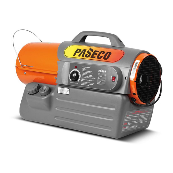
NEVER LEAVE THE HEATER NEVER LEAVE THE HEATER CAUTIONS - SAFETY GUIDE UNATTENDED WHILE BURNING! UNATTENDED WHILE BURNING! CAUTION : Hot while in operation. Do not touch. Keep children, clothing and combustibles away from heater. Minimum Clearances : Outlet: 250cm (8 feet) / Sides, top and rear: 125cm (4 feet) •... - Page 4 2. FEATURES Hot Air Outlet Front Guard Handle Upper Shell Cord Wrap Lower Shell Fuel Cap Fan Guard Fuel Gauge Pressure Gauge Indicator Lamp Fuel Tank Thermostat Knob Power Cord LED Power/Reset Switch Figure 1. IH75000 MODEL...
- Page 5 NEVER LEAVE THE HEATER UNATTENDED WHILE BURNING! Front Handle Hot Air Outlet Handle Louver Cord Wrap Upper Shell Lower Shell Indicator Lamp Fan Guard Thermostat Knob Pressure Gauge Room Temp. Display LED Power/Reset Switch Fuel Cap Power Cord Fuel Gauge Fuel Tank Figure 2.
-
Page 6: Unpacking And Assembly
Louvre Hardware Kit : HW-KFA1001 Hardware Kit : HW-KFA1008 Screws Hardware Kit Part No : Handle Cord Wrap HW-KFA1001 Figure 4. IH75000 MODEL Screws (A) Screws (B) Washers Cotter Pins Wheels Cord Wrap Hardware Kit Part No : HW-KFA1008 Wheels Caps... - Page 7 8) Place front handle on shell flange and insert screws through front handle, shell flange and tighten each screw after each screw is inserted. 2. Assembling handle & cord wrap. 1) Assembling handle : Assemble by method described above for model IH75000. 2) Assembling cord wrap : Assemble by method described above for model IH75000.
- Page 8 NEVER LEAVE THE HEATER UNATTENDED WHILE BURNING! Front Handle Screw(A) Screw(B) Screw Handle Louver Screw(B) Cord Wrap Wheel Flat Washer Wheel Cap Wheel Axle Cotter Pin Extended Hub Figure 8. Wheel and Handle Assembly, IH125000/IH170000 Models Only NOTE : Heater should be inspected before each use, and at least annually by a qualified service person. 4.
- Page 9 If this device activates and turns your heater off it may require service. Internal Shut-Off Temp. Reset Temperature MODELS Plus/Minus 10 Degrees Plus/Minus 10 Degrees IH75000 110˚(C)/230˚(F) 90˚(C)/194˚(F) IH125000 70˚(C)/158˚(F) 40˚(C)/104˚(F) IH170000 70˚(C)/158˚(F)
-
Page 10: To Start Heater
Provide a fresh air opening of at least 2,800 sq. cm (3 sq. feet) for each 100,000 BTU rating. Provide extra fresh air if more heaters are being used. Example : A IH75000 heater requires one of the following: • a two-car garage door raised 15.24 cm (six inches) •... - Page 11 NEVER LEAVE THE HEATER UNATTENDED WHILE BURNING! C.) LOUVRE Louvre CAUTION : RISK OF BURN The Louvre is very hot in operation and after shut-off. Never touch or control angle while still hot. - Louvre’s angle can be controlled by the handle for arrow direction as shown in Figure 10.
-
Page 12: Maintenance
These Screws attach Upper Rear and Lower shells Screw together. (See Figure 13) (IH75000 Model Only.) -Remove Screws along each side of heater using medium phillips screwdriver. These Figure 13. Upper Shell Removal. Screws attach Upper and Lower shells together. - Page 13 NEVER LEAVE THE HEATER UNATTENDED WHILE BURNING! D.) FAN BLADES CLEAN EVERY SEASON OR AS NEEDED. -Remove upper shell(See 11 page.) Set Screw -Use 1/8" allen wrench to loosen set screw which holds Fan Blade to motor shaft. Motor Shaft Flush - Slip Fan Blade off motor shaft.
- Page 14 NEVER LEAVE THE HEATER UNATTENDED WHILE BURNING! F.) SPARK PLUG CLEAN AND REGAP EVERY 600 HOURS Screw OF OPERATION OR REPLACE AS NEEDED. - Remove upper shell (See page 11). - Remove fan (See page 11). - Remove ignitor wire from spark plug. Spark Plug - Remove spark plug from nozzle adaptor using mediumphillips screwdriver.
-
Page 15: Pump Pressure Adjustment
Turn Relief Valve counter-clockwise to decrease pressure. Set Pump pressure according to the chart below. -Stop Heater(See Operation, Page 9). MODE PUMP PRESSURE PRESSURE GAUGE IH75000 3 psi 4 psi IH125000 Pressure Gauge 5 psi IH170000 Figure 20. Adjusting Pump Pressure NOTE: USE ONLY ORIGINAL EQUIPMENT REPLACEMENT PARTS. -
Page 16: Replacing Fuse
NEVER LEAVE THE HEATER UNATTENDED WHILE BURNING! 10. REPLACING FUSE NOTICE : This heater is fuse protected. If your heater fails to ignite, DO NOT RETURN YOUR HEATER TO THE STORE. Please follow the simple instruction below to inspect and change the fuse. PROCEDURE FOR REPLACING FUSE WARNING : SHOCK HAZARD To prevent personal injury, unplug the power cord before replacing fuse. -
Page 17: Troubleshooting Guide
NEVER LEAVE THE HEATER UNATTENDED WHILE BURNING! 11. TROUBLE SHOOTING GUIDE TROUBLE POSSIBLE CAUSE CORRECTIVE ACTION Heater ignites but MAIN PCB 1. Wrong pump pressure 1. See Pump Pressure Adjustment, assembly shuts heater off after Page 14. a short period of time. 2. -
Page 18: Wiring Diagram
NEVER LEAVE THE HEATER UNATTENDED WHILE BURNING! 12. WIRING DIAGRAM A) WIRING DIAGRAM(IH75000) CONTROL PCB SPARK PLUG BLACK GRAY IGNITOR GRAY BLACK POWER LAMP (LED) ORANGE BLACK PUMP WHITE MOTOR ROOM SENSOR CAPACITOR GREEN 7uF/400VAC THERMOSTAT CN2(AC2)/ BLUE (TEMP. CONTROL) -
Page 19: Specifications
NEVER LEAVE THE HEATER UNATTENDED WHILE BURNING! 13. SPECIFICATIONS 368mm 706mm IH75000 IH125000 IH170000 686mm 686mm 815mm 937mm 470mm 470mm IH125000/IH170000 MODEL IH75000 IH125000 IH170000 60,000BTU (16.5kW) 105,000BTU (29kW) 150,000BTU (41kW) Heating Output Fuel Consumption - Litre/Hr. Fuel Tank Capacity - Litre Pump Pressure p.s.i. - Page 20 NEVER LEAVE THE HEATER UNATTENDED WHILE BURNING! 14. EXPLODED PARTS DRAWING(IH75000Model Only) Burner Head Assembly 20-3 20-8 20-5 20-7 20-2 20-1 20-4 20-6 31-2 31-1 Motor Pump Assembly 22-5 22-5 22-6 22-9 22-8 22-1 22-10 22-14 22-3 22-16 22-17 22-4 22-18 22-7 22-15...
- Page 21 NEVER LEAVE THE HEATER UNATTENDED WHILE BURNING! 15. PARTS LIST(IH75000 Model Only) KEY NO. DESCRIPTION PART NO. KEY NO. DESCRIPTION PART NO. Pump Body Fuel Tank Assembly 2151-0016-00 22-5 3541-0022-00 Bolt-BH Special Fuel Gauge 2156-0023-00 22-6 4321-0198-00 Insert Fuel Gauge Cap...
- Page 22 NEVER LEAVE THE HEATER UNATTENDED WHILE BURNING! 15. EXPLODED PARTS DRAWING(IH125000/IH170000 Models Only) Burner Head Assembly 20-3 20-8 20-5 20-7 20-2 20-1 20-4 20-6 31-2 31-1 Motor Pump Assembly 22-2 22-3 22-6 22-7 22-10 22-9 22-11 22-1 22-15 22-4 22-17 22-18 22-5 22-19...
- Page 23 NEVER LEAVE THE HEATER UNATTENDED WHILE BURNING! 17. PARTS LIST(IH125000/IH170000 Models Only) PART NO. KEY NO. DESCRIPTION IH125000 IH170000 2151-0012-00 2151-0011-00 Fuel Tank Assembly 2156-0022-00 2156-0022-00 Fuel Gauge 3231-0123-00 3231-0123-00 Fuel Gauge Cap 3231-0122-00 3231-0122-00 Fuel Cap 2155-0010-00 2155-0010-00 Fuel Filter Assembly 2151-0043-01 2151-0044-01 Shell Lower Assembly...
- Page 24 NEVER LEAVE THE HEATER UNATTENDED WHILE BURNING! PART NO. KEY NO. DESCRIPTION IH125000 IH170000 3231-0181-00 3231-0181-00 Elbow 22-12 4329-0016-00 4329-0016-00 Flange Bolt 22-13 3631-0005-00 3631-0005-00 Lint Filter 22-14 2155-0004-00 2155-0004-00 Output Filter 22-15 3631-0005-00 3631-0005-00 Intake Filter 22-16 End Filter Cover 3221-0029-00 3221-0029-00 22-17...
-
Page 25: Parts List (Wheels And Handle)
NEVER LEAVE THE HEATER UNATTENDED WHILE BURNING! 18. PARTS LIST (WHEELS AND HANDLE) 1) IH75000 MODEL PART NO. DESCRIPTION IH75000 Handle 3231-0125-00 Cord Wrap 3231-0056-00 Hardware Kit HW-KFA1001 2) IH125000/IH170000 MODELS PART NO. KEY NO. DESCRIPTION IH125000 IH170000 Handle Front...
Need help?
Do you have a question about the IH75000 and is the answer not in the manual?
Questions and answers
Where do i get replacement filters for model #ih125000 deisel heater ?