
Summary of Contents for Sofar solar ESI Series
- Page 1 ESI Series User Manual Intelligent Residential System Product Model: ESI 3~6K-S1-HA1~6 S h e n z h e n S O FA R S O L A R C o . , L t d .
-
Page 2: Table Of Contents
ESI 3~6K-S1-HA1~6 user manual Contents Preface ........................III 1. Basic Safety Information ...................1 1.1. Requirement for Installation and Maintenance ........1 1.2. Symbols and signs ..................6 2. Product Introduction ..................9 2.1. Product overview ................... 9 2.2. Product Model Description ..............10 2.3. - Page 3 ESI 3~6K-S1-HA1~6 user manual 4.5. Install the cover ..................52 4.6. Parallel system ..................53 4.7. System Electrical Topology ..............55 5. Commissioning ....................56 5.1. Checking Before System Starting ............56 5.2. Electrify for the First Time(Important) ...........56 5.3. Menu ....................59 6.
-
Page 4: Preface
Unless additional terms and conditions in your contract, the company does not make any statement or guarantee on the contents of this document. In addition, the term "Product" as described in this document refers broadly to "ESI Series products" Save this Instruction This manual must be considered as an integral part of the equipment. - Page 5 Scope of Validity This product manual describes the installation, electrical connections, commissioning, maintenance and troubleshooting of ESI Series products. Target Group This manual is for qualified electricians. The tasks described in this manual only can be performed by qualified electricians.
- Page 6 ESI 3~6K-S1-HA1~6 user manual “Attention”indicates there are potential risks, if fail to prevent, may lead to equipment cannot normally or property damage. Attention “Note”provides additional information and tips that are valuable for the optimal operation of the product, will help you to solve a problem or save your time.
-
Page 7: Basic Safety Information
ESI 3~6K-S1-HA1~6 user manual 1. Basic Safety Information Outlines of this Chapter Please read the instruction carefully. Faulty operation may cause serious injury or death . If you have any question or problem when you read the following information, please contact SHENZHEN SOFARSOLAR CO., Ltd. - Page 8 The maintenance personnel of this product must understand the knowledge and skills related to inverter and battery maintenance. ESI Series products are transformerless inverter which requires the positive pole and negative pole of the PV array are NOT grounded. Otherwise, it will cause inverter failure.
- Page 9 ESI 3~6K-S1-HA1~6 user manual Installation and maintenance personnel requirements When the product is in the running state, some parts may be electrified and hot. Improper use, improper installation or operation may result in serious injury to person or property. Transport, loading, unloading, installation, start-up and maintenance operations must be performed by a qualified electrical engineer (all accident precautions in force in the user's country must be followed!) SOFARSOLAR will not be responsible for any personal injury or property injury...
- Page 10 ESI 3~6K-S1-HA1~6 user manual result in battery leakage, breakage, explosion, or fire. Transportation Requirement Shipping complies with the IMDG CODE and the International Maritime Dangerous Goods CODE. For land transportation, comply with ADR or JT T617 shipping requirements Meet the regulatory requirements of the transport regulatory authorities of ...
- Page 11 ESI 3~6K-S1-HA1~6 user manual Touching the utility grid or the terminal conductors can lead to lethal electric shock or fire! Do not touch non-insulated cable ends, DC conductors and any live components. Danger Attention to any electrical relevant instruction and document. Enclosure or internal components may get hot during operation.
-
Page 12: Symbols And Signs
ESI 3~6K-S1-HA1~6 user manual Electromagnetic radiation from the product may be harmful to health! Please do not continue to stay away from the product in less than 20cm when it is working Danger 1.2. Symbols and signs High voltage of inverter may be harmful to health! Only certified engineer can operate the product;... - Page 13 ESI 3~6K-S1-HA1~6 user manual The inverter module operates at high voltages. Prior to performing any work Caution of high voltage and on the product, disconnect the product electric shock from voltage sources. All work on the product must be carried out by qualified persons only.
- Page 14 ESI 3~6K-S1-HA1~6 user manual The product complies with the RCM (Regulatory requirements of the applicable Compliance Mark) Australian standards Sings on the battery module Symbols Name Explanation After the battery is powered on, there is a high voltage. After the battery is This is a residual powered off, the internal capacitor is voltage in the...
-
Page 15: Product Introduction
2.1.1. Product brief introduction ESI series single-phase household energy storage system consists of inverter module and lithium battery module. It adopts modular design and can be stacked with building blocks. The battery capacity ranges from 5kWh to 30kWh. The system can manage the energy of photovoltaic, battery, utility grid and load according to the actual application, and realize the optimal distribution of system energy. -
Page 16: Product Model Description
ESI 3~6K-S1-HA1~6 user manual Figure 2-1 ESI series application principle diagram 2.2. Product Model Description ESI series inverter model: Figure 2-2 Inverter Model Identifiers Table 2-1 Inverter Model demonstration Identifiers Meaning Specification Stacked optical storage all in one Product Model ①... - Page 17 ESI 3~6K-S1-HA1~6 user manual Single-phase hybrid energy storage Inverter Model ③ inverter ESI series battery module model: Figure 2-3 Battery module model identifiers Table 2-2 Battery module model demonstration Identifiers Meaning Specification SOFARSOLAR BTS series battery Product series name ①...
-
Page 18: Product Capacity Description
HA3 means 3 battery modules ④ 2.3. Product Capacity Description The ESI series residential energy storage system supports power and capacity expansion and supports up to six inverter modules in parallel. One inverter module supports up to six batteries expansion modules. - Page 19 ESI 3~6K-S1-HA1~6 user manual Copyright © Shenzhen SOFARSOLAR Co., Ltd...
-
Page 20: Product Appearence
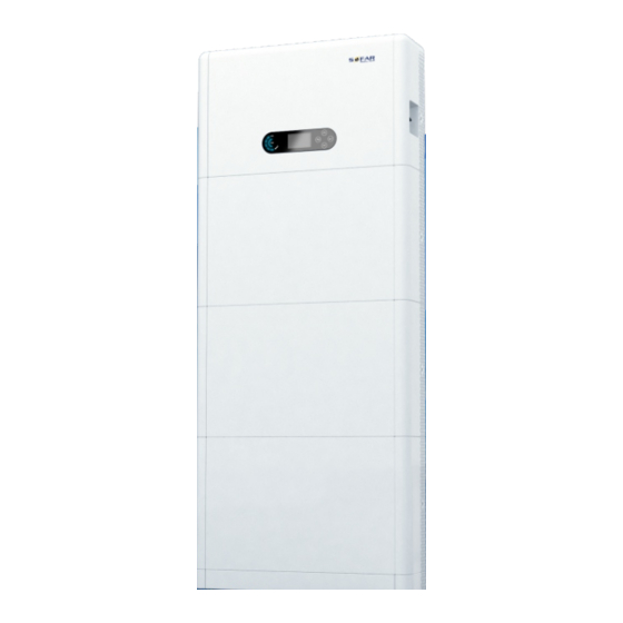
ESI 3~6K-S1-HA1~6 user manual 2.4. Product Appearance Front Side Back Side Figure 2.6 Product front side and back side 1 Inverter 2 DC Switch 3 LCD display screen 4 Battery Module Pedestal 6 Inverter Radiator 7 Battery Module Radiator Copyright © Shenzhen SOFARSOLAR Co., Ltd... - Page 21 ESI 3~6K-S1-HA1~6 user manual 2.4.1. Inverter Port Right side port Left side port Figure 2-7 Inverter port diagram 1 Grid connection port 2 Load connection port 3 Inverter signal port 4 DC Switch 5 PV input port 6 WIFI/4G port 7 Battery black start switch 8 Battery input switch 9 Battery connection port 10 Battery signal port...
-
Page 22: Buttons And Indicator Lights
ESI 3~6K-S1-HA1~6 user manual 2.4.2. Battery module port Battery Left Side Battery Right Side Figure 2-8 Battery module port diagram Battery output terminal Battery input terminal 3 Link Port In 4 Link Port Out 2.5. Buttons and indicator lights Figure 2-9 Buttons and indicator lights 1 System power indicator 2 System status indicator 3 Buttons 4 LCD screen Copyright ©... - Page 23 ESI 3~6K-S1-HA1~6 user manual 2.5.1. Buttons Press “back” to the previous screen or enter the main interface. Press “up” to the upper menu option or value plus 1. Press “down” to the lower menu option or value minus 1. ...
-
Page 24: Product Label
ESI 3~6K-S1-HA1~6 user manual 40%-60% 20%-40% The battery capacity is insufficient, and the battery 0-20% generates a low voltage alarm. 2.6. Product label Figure 2-10 Battery module label Copyright © Shenzhen SOFARSOLAR Co., Ltd... - Page 25 ESI 3~6K-S1-HA1~6 user manual Figure 211 Inverter label Copyright © Shenzhen SOFARSOLAR Co., Ltd...
-
Page 26: Product Installation
ESI 3~6K-S1-HA1~6 user manual 3. Product Installation 3.1. Checking Before Installation Checking Outer Packing Materials Before opening the battery and inverter package, check whether the outer package is damaged, such as holes and cracks, and check the inverter and battery model. If any damage is found or the inverter and battery model does not match your requirements, please do not open the product package and contact your distributor as soon as possible. - Page 27 ESI 3~6K-S1-HA1~6 user manual Left side cover 1pcs Right side cover 1pcs Hanging rack 2pcs Fixed support rack B 2pcs Side connector 2pcs SEM screw M4*10 6pcs Hexagon screws M5*10 4pcs Hexagon screws M6*14 4pcs PV+ input terminal 2pcs Copyright © Shenzhen SOFARSOLAR Co., Ltd...
- Page 28 ESI 3~6K-S1-HA1~6 user manual PV- input terminal 2pcs Metal terminals secured to PV+ input power 2pcs cables Metal terminals secured to PV- input power 2pcs cables Battery positive terminal + 1pcs input terminal plastic case Parallel connection cable 1pcs Battery negative terminal + 1pcs input terminal plastic case Battery positive + input...
- Page 29 ESI 3~6K-S1-HA1~6 user manual AC connector 1pcs Load connector 1pcs Single phase electronic rail mounting meter & current 1pcs(optional) transformer(CT) Current transformer(CT) 1pcs COM 24pin connector 1pcs Manual 1pcs The warranty card 1pcs Quality Certificate 1pcs Copyright © Shenzhen SOFARSOLAR Co., Ltd...
- Page 30 ESI 3~6K-S1-HA1~6 user manual Battery packing list Pictures Description Quantity Battery module 1pcs Side panel 2pcs Battery power connection 2pcs cable Battery signal connection 1pcs cable Fixed support rack A 2pcs Side connector 2pcs Fixed support rack B 2pcs Ground Wire 1pcs Copyright ©...
-
Page 31: Installation Tools
ESI 3~6K-S1-HA1~6 user manual Hexagon SEM screws M6*14 4pcs SEM screws M4*10 10pcs Expansion bolt M6*60 2pcs Terminal resistance 1pcs Quality Certificate 1pcs 3.2. Installation Tools Before installation, prepare the following tools: Tool Model Function Hammer drill Used to drill holes on the wall. - Page 32 ESI 3~6K-S1-HA1~6 user manual Remove and install screws Screwdriver and wires Remove and install screws Cross screwdriver and wires Wire stripper Used to peel cable Secure the backplane and M6 socket head wrench inverter Use to crimp cable on grid Crimping Tool side, load side and CT extensive cable...
-
Page 33: Installation Environment
ESI 3~6K-S1-HA1~6 user manual Ensure the rear panel is Level properly installed Installer wear when ESD gloves installing product Installer wear when drill Safety goggle holes Installer wear when drill Mask holes Remove the output Removal Tool terminal of the battery module sleeve Install Fixed support rack... - Page 34 ESI 3~6K-S1-HA1~6 user manual The product should be placed in a well-ventilated place; There are no inflammable and explosive objects near the installation position of the product; The product system inverter AC over-voltage level is three; The highest altitude of the installation environment is 4000m. ...
-
Page 35: Installation Space
ESI 3~6K-S1-HA1~6 user manual 3.4. Installation Space To ensure sufficient space for installation and heat dissipation, reserve sufficient space around the ESI series household energy storage system. The requirements are as follows: Figure 3-2 I nstallation space diagram Copyright © Shenzhen SOFARSOLAR Co., Ltd... -
Page 36: Product Installation
ESI 3~6K-S1-HA1~6 user manual 3.5. Product Installation Figure 3-3 ESI series installation dimensions diagram Pedestal installation Procedure: 1)Place the pedestal against a wall and keep it 10 to 25mm away from the wall. Adjust the hole positions using a level, and mark the hole positions using a marker. - Page 37 ESI 3~6K-S1-HA1~6 user manual securely installed. 3 ) Use a marker to mark holes for securing the battery modules and inverters based on the dimensions shown in Figure 3-3. ③ ① Inverter Levelling instrument Third Battery 60mm PACK Second Battery PACK Wall Baseboard...
- Page 38 ESI 3~6K-S1-HA1~6 user manual Procedure: 1)Align the first battery module on the floor pedestal. 2 ) Install connectors on both sides and tighten the six screws using a cross screwdriver. 3 ) Install the remaining battery modules and inverters from bottom to top. (Before installing the next module, ensure that the screws on the side connectors of the previous module are firmly installed.) Figure 3-5...
- Page 39 ESI 3~6K-S1-HA1~6 user manual Support rack installation: Procedure: 1)Drill holes with a hammer drill (φ 8mm, depth range 60-65 mm). Reposition and drill the holes, if the original one has a large deviation. 2)Install the support rack B on the wall, and fastening expansion bolt. 3)Adjust the support rack A, make sure the holes are matched between rack A and rack B.
-
Page 40: Electrical Connection
ESI 3~6K-S1-HA1~6 user manual 4. Electrical Connection 4.1. Attentions Before Connection The voltage in the power conversion circuit of this product is very high. Fatal danger of electric shock or severe burns. All electrical connections of photovoltaic modules, inverters and battery systems must be carried out by qualified personnel. -
Page 41: Electrical Connection For Internal System
ESI 3~6K-S1-HA1~6 user manual Table 4-1 Cables prepared by customers Cable Recommended specifications PV connection cable UL10269 12AWG AC Grid connection cable UL10269 8AWG EPS connection cable UL10269 10AWG Grounding cable UL10269 8AWG 4.3. Electrical Connection for Internal System 4.3.1. Internal protection grounding cable connection Connect the grounding cables of the battery module and inverter as shown in Figure 4.3.1-1. - Page 42 ESI 3~6K-S1-HA1~6 user manual Figure 4-1 Internal grounding cable connection 4.3.2. Power cables connection As shown in Figure 4-2, connect the power ports (BAT+,BAT-) of the inverter to the cascading positive and negative power cables (B+,B -) of the battery module. Connect the remaining battery modules from top to bottom, and secure the cables with cable ties.
- Page 43 ESI 3~6K-S1-HA1~6 user manual If the system capacity is greater than 15kWh, the batteries are connected to the inverter's battery input interface in two independent groups. Figure 4-2 Connection of battery internal DC terminal 4.3.3. Internal communication cable connection Connect the communication terminals of the inverter and battery module from top to bottom according to 4-3 in the following figure, and secure them with cable ties.
- Page 44 ESI 3~6K-S1-HA1~6 user manual module in the system. Figure 4-3 Internal signal cable connection 4.3.4. Data collector connection Connect the standard WIFI/4G collector in the inverter package according to 4-4 in the following figure. Copyright © Shenzhen SOFARSOLAR Co., Ltd...
-
Page 45: External Electrical Connection
ESI 3~6K-S1-HA1~6 user manual Figure 4-4 WIFI/4G connection 4.4. External Electrical Connection 4.4.1. External ground Connection of the PGND cable Procedure 1 Crimp OT terminals Precautions: When stripping the cable, do not scratch the core of the cable. The conductor crimping plate of an OT terminal is pressed to form a cavity that ... - Page 46 ESI 3~6K-S1-HA1~6 user manual Figure 4-5 Diagram of Crimping OT terminals Procedure 2 The OT terminal is crimped properly, and the ground cable is connected to the position shown in the following figure. Figure 4-6 Connect the grounding wire Copyright © Shenzhen SOFARSOLAR Co., Ltd...
- Page 47 ESI 3~6K-S1-HA1~6 user manual 4.4.2. PV module connection Table 4-2 Recommended DC input cable specifications CAS (mm External cable diameter(mm Range Recommended value 4.0~6.0 4.5~7.8 Connection Procedure: Step 1: Prepare PV positive and negative power cables; 1. Positive connector 2. Negative connector Figure 4-7 Prepare PV positive and negative power cable Step 2 :...
- Page 48 Ensure that the DC voltage of each PV string is less than 600V and the polarity of PV cables are correct. Insert the positive and negative connectors into the corresponding PV region of the ESI series inverter until a click is heard. As the figure 4-9 showing.
- Page 49 ESI 3~6K-S1-HA1~6 user manual 4.4.3. Grid connection Install AC wiring terminals Take out AC wiring terminals from the carton of the inverter, strip and install cables according to the cable specifications listed in Table 4-1,The schematic diagram of wire stripping is shown in figure 4- 11 Figure 4-11 Wire stripping size Installation Step...
- Page 50 ESI 3~6K-S1-HA1~6 user manual Tighten the nut with an open wrench The body is inserted into the core and a and make a "click" sound click is heard Installation complete Insert the female end of the wire into the male end and hear a "click" sound Figure 4-12 Installation Procedure Diagram Removal Step...
- Page 51 ESI 3~6K-S1-HA1~6 user manual Hold the unlocking buckle with one hand Remove the red circles on both sides and rotate it in the direction indicated, using a screwdriver while rotate the nut in the opposite direction with the other hand Figure 4-13 Removal procedure Connect the AC wiring terminals to the corresponding AC Grid ports, as shown in the following figure.
- Page 52 ESI 3~6K-S1-HA1~6 user manual 4.4.4. EPS connection According to the cable specifications given in Table 4-1, peel the cable according to the following figure 4-15. Then install the EPS connector according to 4-16. Finally, insert the installed EPS connector into the corresponding position of the inverter according to Figure 4-17.
- Page 53 ESI 3~6K-S1-HA1~6 user manual Screw locking nut into main body, Installation complete torque 2.5± 0.5N.m Figure 4-16 EPS Connector installation Figure 4-17 EPS connection Copyright © Shenzhen SOFARSOLAR Co., Ltd...
- Page 54 ESI 3~6K-S1-HA1~6 user manual 4.4.5. COM-Multi function communication connection Figure 4-18 COM port diagram Table 4-3 Port description Definition Function Comment UC-A RS485 differential signal -A Inverter monitoring 485 signal UC-B RS485 differential signal -B RS485 differential signal + Battery 485 signal RS485 differential signal - MET-A RS485 differential signal -A...
- Page 55 ESI 3~6K-S1-HA1~6 user manual D2/6 D3/7 Current transformer output positive terminal Current transformer communication signal Current transformer output negative pole Link Port Figure 4-18 Link Port diagram Table 4-4 Link Port description Icon Define Function Comment Link Port 1 Parallel signal output Parallel signal port (RJ45)...
- Page 56 ESI 3~6K-S1-HA1~6 user manual The wire stripping is divided into 2 to 9 holes and 12 to 19 holes. The wire stripping size is defined according to the cable connection position size 2-9 position stripper 12-19 hole stripping size Figure 4-19 Schematic diagram of wire stripping size Installation procedure for connecting cables Remove the plug from the plug and...
- Page 57 ESI 3~6K-S1-HA1~6 user manual Insert the plug into the body and plug Screw the lock nut into the main the unwired hole body, torque 2.5± 0.1N.m, complete installation Figure 4-20 Procedure for connecting COM cables Insert the stripped COM connector into the corresponding port of the inverter, as shown in the following figure.
-
Page 58: Install The Cover
ESI 3~6K-S1-HA1~6 user manual 4.4.6. Smart Meter /CT Refer to the COM interface description in table 4-3, the RS485A and RS485B of the electricity meter should be connected to pin6 and pin7 of the COM port of the inverter. Meter Figure 4-22 Smart meter/CT connection diagram 4.5. -
Page 59: Parallel System
ESI 3~6K-S1-HA1~6 user manual Figure 4-23.Install the cover 4.6. Parallel system Refer to figure 4.6-1 below and connect the system in parallel according to the success of the master and slave (up to 6 units). The dip switch inside the COM 24PIN connector of the last system inverter should be moved to the position of 1. - Page 60 ESI 3~6K-S1-HA1~6 user manual Copyright © Shenzhen SOFARSOLAR Co., Ltd...
-
Page 61: System Electrical Topology
ESI 3~6K-S1-HA1~6 user manual 4.7. System Electrical Topology ESI series household energy storage system is mainly composed of PV modules, BTS 5K battery modules, inverters, AC switches, load and distribution units, smart meters /CT, and power grid. Figure 4-25 System Electrical Topology (General) -
Page 62: Commissioning
ESI 3~6K-S1-HA1~6 user manual 5. Commissioning 5.1. Checking Before System Starting Please double check the following items before running The product should be completely fixed on the pedestal bracket, and the connection with the wall should be tight and firm. The PV+/PV- line is firmly connected, the polarity is correct, and the voltage is in line with the accessible range. - Page 63 ESI 3~6K-S1-HA1~6 user manual Turn on the AC circuit breaker between the inverter load port and the emergency load. Press the system power button, and the inverter starts running. The system status indicator is blue.. When the inverter is running, set the following parameters. Table 5- 1 Setting parameter Parameter Comment...
- Page 64 ESI 3~6K-S1-HA1~6 user manual Italia CEI-021 External Europe General Italia CEI0-21 In Areti Cyprus Australia India Australia AU-WA Philippines Australia AU-SA New Zealand Australia AU-VIC Brazil Australia AU-QLD Brazil LV Australia AU-VAR Brazil 230 Australia AUSGRID Brazil 254 Australia Horizon Slovakia VSD Spain RD1699 Slovakia SSE...
-
Page 65: Menu
ESI 3~6K-S1-HA1~6 user manual It’s very important to make sure that you have selected the correct country code according to requirements of local authority. Please consult qualified electrical engineer or personnel from electrical safety authorities about this. Caution SHENZHEN SOFARSOLAR Co., Ltd. is not responsible for any consequences arising out of incorrect country code selection. - Page 66 ESI 3~6K-S1-HA1~6 user manual In the main interface, press“ ”button to enter Grid/Battery/PV parameter page. Main interface Grid Output Information Grid(V)....***.*V AC Power ....**.**kW Frequency....**.**Hz Battery Information Batt....****.*V Batt Curr....**.**A Batt Power....**.*kW Batt Temp......*℃ Batt SOC......**% Batt Cycles....*T PV Information PV1 Voltage ..****.*V Current....**.**A...
- Page 67 ESI 3~6K-S1-HA1~6 user manual Main Interface 1.System Settings 2.Advanced Settings 3.Energy Statistic 4.System Information 5.Event List 6.Software Update 7.Battery Real-time Information 5.3.1. System Setting 1. System Setting 1.Language Setting 2.System Time 3.Safety Param. 4.Energy Storage Mode 5.Auto Test 6.Input channel Configuration 7.EPS Mode 8.Communication Addr.
- Page 68 ESI 3~6K-S1-HA1~6 user manual 2. System Time Set the system time for the inverter. 2.Time Time 2022-05-13 17:07:00 3. Safety Parameter. User can modify the Safety Parameter. of the machine through the USB flash disk, and the user needs to copy the parameter information that needs to be modified into the USB flash disk card in advance.
- Page 69 ESI 3~6K-S1-HA1~6 user manual 4)If the PV power is less than the load power, If the battery is fully charged or has the inverter will supply power to the load reached its maximum charging power, the through battery remaining power is sent to the grid (with discharge.
- Page 70 ESI 3~6K-S1-HA1~6 user manual If your family normally go to work/school on weekdays & stay at home on weekends, which means the home electricity consumption is much higher on weekends. Thus, you need to store some cheap electricity on weekends only. This is possible using our Time-of-use mode.
- Page 71 ESI 3~6K-S1-HA1~6 user manual 3.Timing Mode Timing Mode Rules. 0: Enabled/Disabled Charge Start 22 h 00 m Charge End 05 h 00 m Charge Power 02000 W DisCharge Start 14 h 00m DisCharge End 16 h 00m DisCharge Power 02500 W 4.4 Passive Mode 4.Passive Mode...
- Page 72 ESI 3~6K-S1-HA1~6 user manual 3)If PV generation < LOAD consumption (ΔP > 100W), inverter will discharge battery. 6. Communication Addr 6. Communication Addr 1. Communication Addr 2.Baud Rate 5.3.2. Advanced Setting Input 0001 2. Advanced setting 1.Battery Parameter 2.Battery Activation 3.Anti Reflux 4.IV Curve Scan 5.Logic interface...
- Page 73 ESI 3~6K-S1-HA1~6 user manual 10.Set ElevtricityMter 1. Battery Parameter Battery Number 1.Battery Parameter Battery1 1 Battery Quantity Group 1 represents the number of cascading battery modules for the BAT1 port of the inverter. Group 2 represents the number of battery modules connected to the BAT2 port of the inverter.
- Page 74 ESI 3~6K-S1-HA1~6 user manual 3. Depth of Discharge Discharge Depth EPS Discharge Depth EPS Safety Buffer 2. Anti Reflux Users can limit the maximum power sent from the system to the grid by enabling Anti Reflux control. Counter current power is the maximum power expected to be sent to the grid (e.g., 0KW means no energy is fed into the grid).
- Page 75 ESI 3~6K-S1-HA1~6 user manual Enable 4.Logical Interface Control Disable 5. Factory Reset 5.Factory Reset 1.Clear Energy Data 2.Clear Events Clear the total energy yield of the inverter. 1.Clear Generated Cancel Enter 0001 Power Clear the history events of the inverter. 2.Clear List Cancel 6.
- Page 76 ESI 3~6K-S1-HA1~6 user manual 7. Bluetooth Reset Please Succeed 7.Bluetooth Reset Confirm! 8. CT Calibration Used to calibrate the orientation and phase of the CT. The battery should be charged or discharged when using this feature. Succeed/ Start CT Calibration ? 8.CT Failed Calibration...
- Page 77 ESI 3~6K-S1-HA1~6 user manual Discharge......***kWh Year PV ......***kWh Load ......***kWh Export......***kWh Import......***kWh Charge......***kWh Discharge......***kWh Lifetime PV ......***kWh Load ......***kWh Export......***kWh Import......***kWh Charge......***kWh Discharge......***kWh 5.3.4. System Information 1.Inverter Info 4. .System Information 2.Battery Info 3.Safety Info 4.Debug Info 3.PCU Info Copyright © Shenzhen SOFARSOLAR Co., Ltd...
- Page 78 ESI 3~6K-S1-HA1~6 user manual 1. Inverter Info Inverter Info (1) Product SN Hardware Version Power Level Safety Firmware Version Inverter Info (2) Software Version Country Safety Lib Version Inverter Info (3) Input Channel 1 Input Channel 2 Input Channel 3 Input Channel 4 Inverter Info (4) Energy Storage Mode...
- Page 79 ESI 3~6K-S1-HA1~6 user manual 2.Battery Info Battery 1 Info (1) Battery Type Battery Capacity Discharge Depth EPS Safety Buffer Battery 1 Info (2) Max Charge (A) Max Discharge (A) Charge Start Charge End Safety parameters Safety param OVP 1 OVP 2 UVP 1 UVP 2 Safety param...
- Page 80 ESI 3~6K-S1-HA1~6 user manual 5.3.5. Event List Once a fault occurs, the fault information is displayed on the event list page. The event list displays the current event records, including the event ID and occurrence time of each event. You can access the event list screen on the main screen to view detailed information about real-time events.
- Page 81 ESI 3~6K-S1-HA1~6 user manual Step 7 If the following error occurs, upgrade again. If this situation persists for several times, contact technical support for help. USB error DSPM file error DSPS file error ARM file error Upgrading DSPM fail Upgrading DSPS fail Upgrading ARM fail Step 8 After the upgrading, turn off the DC switch, wait for the LCD screen to go off,...
-
Page 82: Trouble Shooting And Maintenance
ESI 3~6K-S1-HA1~6 user manual 6. Trouble shooting and maintenance 6.1. Troubleshooting This section describes the potential errors for this product. Please read carefully for the following tips when doing the troubleshooting: View the warning or error information and error codes displayed on the display ... - Page 83 ESI 3~6K-S1-HA1~6 user manual be found in the fault history. For the machine equipped with WiFi/4G data collector, the alarm information can be seen on the corresponding monitoring website or received through the APP on the mobile phone. Event list ...
- Page 84 ESI 3~6K-S1-HA1~6 user manual local electrical grid operator. ID005 Charge Leakage Fault ID006 OVRT function is faulty ID007 LVRT function is faulty ID008 Island protection error Transient overvoltage of grid ID009 voltage 1 Transient overvoltage of grid ID010 voltage 2 Internal faults of inverter, switch ID011 Power grid line voltage error...
- Page 85 ESI 3~6K-S1-HA1~6 user manual DCV sampling error ID023 Input current sampling error ID024 DCI sampling error(AC) ID025 Branch current sampling ID026 Leakage current consistency ID029 error Grid voltage consistency error ID030 DCI consistency error ID031 SPI communication error ID033 (DC) SPI communication error ID034 (AC)
- Page 86 ESI 3~6K-S1-HA1~6 user manual Check ac output PE wire for Ground fault ID043 grounding. Check the PV input mode (parallel/independent mode) Error setting input mode ID044 setting of the inverter. If not, change the PV input mode Check whether the CT connection CT Fault ID045 is correct...
- Page 87 ESI 3~6K-S1-HA1~6 user manual Temperature 1 protection ID057 Temperature 2 protection ID058 Module 1 temperature ID059 protection Module 2 temperature ID060 protection Module 3 temperature ID061 protection Unbalanced bus voltage RMS ID065 Internal faults of inverter, switch The transient value of bus OFF inverter, wait for 5 minutes, ID066 voltage is unbalanced...
- Page 88 ESI 3~6K-S1-HA1~6 user manual inconsistent with battery specifications LLC BUS overvoltage ID071 protection Inverter bus voltage RMS ID072 software overvoltage Inverter bus voltage instantaneous value software ID073 overvoltage Battery overcurrent protection ID081 by software Internal faults of inverter, switch Dci overcurrent protection OFF inverter, wait for 5 minutes, ID082 then switch ON inverter.
- Page 89 ESI 3~6K-S1-HA1~6 user manual BuckBoosthardware ID099 overflows Reserved ID100 PV hardware overflows ID102 Ac output hardware overflows ID103 Meters communication fault ID105 Overload Protection 1 Check whether the inverter works ID110 in overload state. Overload Protection 2 ID111 Overload Protection 3 ID112 Make sure the inverter is installed in a place free from direct...
- Page 90 ESI 3~6K-S1-HA1~6 user manual Volatge loading ID117 Battery low voltage protection Check whether the battery voltage ID124 is too low or the battery discharge Battery low voltage shutdown ID125 depth is too low. Output hardware overcurrent Internal faults of inverter, switch ID129 permanent failure OFF inverter, wait for 5 minutes,...
- Page 91 ESI 3~6K-S1-HA1~6 user manual SOFARSOLAR technical support. Input hardware overcurrent Internal faults of inverter, switch ID139 permanent failure OFF inverter, wait for 5 minutes, then switch ON inverter. Check Relay permanent fault ID140 whether the problem is solved. If not, please contact Bus Unbalanced permanent ID141 SOFARSOLAR technical...
- Page 92 ESI 3~6K-S1-HA1~6 user manual (DC) SCI communication error ID154 (AC) SCI communication error ID155 (Fuse) Contact technical support to Inconsistent software versions ID156 obtain the upgrade software. Lithium battery 1 ID157 Make sure the battery you use is communication error compatible with the inverter.
- Page 93 ESI 3~6K-S1-HA1~6 user manual Check whether fan 1 of the Fan 1 fault ID169 inverter works properly。 Check whether fan 2 of the Fan 2fault ID170 inverter works properly Check whether fan 3 of the Fan 3 fault ID171 inverter works properly Check whether fan 4 of the Fan 4 fault ID172...
- Page 94 ESI 3~6K-S1-HA1~6 user manual BMS Short circuit alarms ID182 BMS Version inconsistency ID183 BMSCAN Version ID184 inconsistency BMS CAN Version is too low ID185 Communication failure of arc ID189 equipment ID401 Acr fault ~ ID432 Copyright © Shenzhen SOFARSOLAR Co., Ltd...
-
Page 95: Daily Maintenance
ESI 3~6K-S1-HA1~6 user manual 6.2. Daily Maintenance This product usually does not require maintenance or calibration, but ensure that the inverter and the heat sink of the battery module are not covered by dust or dirt. Clean the inverter and battery modules: ... - Page 96 ESI 3~6K-S1-HA1~6 user manual Recharge Requirements During Normal Storage When the battery is stored for a long time, you need to perform regular maintenance. If the storage time is close to that shown in the following table, arrange supplementary power supply in time. Table 6-2 Recharge conditions when in storage Storage Relative Humidity of...
- Page 97 ESI 3~6K-S1-HA1~6 user manual -10℃~25℃ ≤15 days 25℃~45℃ ≤7 days 30%≤SOC≤60% ≤12 hours -10℃~45℃ Copyright © Shenzhen SOFARSOLAR Co., Ltd...
-
Page 98: Technical Parameters
ESI 3~6K-S1-HA1~6 user manual 7. Technical Parameters System Parameters System Schematic Rated output power 3000~6000W Qty.of batteries Battery total energy[1] 5kWh 10kWh 15kWh 20kWh 25kWh 30kWh Degree of protection IP65 Ambient temperature -10℃~+50℃ range[2] Allowable relative 5%~95% humidity range Max. operating 4000m altitude[3] Weight... - Page 99 ESI 3~6K-S1-HA1~6 user manual 708*170*13 708*170*13 708*170*17 10mm 10mm 30mm 708*170*890 708*170*13 708*170*17 Dimension(W*D*H) 10mm 30mm 708*170*90 708*170*13 708*170*13 20mm 20mm Display LCD & APP+Bluetooth Communication RS485/Bluetooth/Ethernet, Optional: WiFi//4G/GPRS Inverter Module Model ESI 3K-S1 ESI 5K-S1 ESI 6K-S1 3.68K-S1 4K-S1 4.6K-S1 5K-S1-A Rated battery voltage...
- Page 100 ESI 3~6K-S1-HA1~6 user manual MPPT Rated grid voltage L/N/PE, 230V,50Hz / 60Hz Grid voltage range 180Vac-276Vac (According to local standard) Rated AC power 3000W 3680W 4000W 4600W 5000W 5000W 6000W Max. AC power output 3300VA 3680VA 4400VA 4600VA 5500VA 5000VA 6600VA to utility grid Rated...
- Page 101 ESI 3~6K-S1-HA1~6 user manual Model BTS 5K Battery Type Battery module energy 5120Wh Depth of discharge (DOD) 0~90% adjustable Rated Power 2500W Topology Transformer isolation Dimension(W*D*H) 708*170*420mm Weight 50kg UN38.3, IEC62619, IEC62040-1, SAA etc. Certification Certification EN 61000-6-2, EN 61000-6-3, EN 61000-3-2, EN 61000-3-3, EN 61000-3-11, EN 61000-3-12 Safety IEC 62109-1/2, IEC 62040-1, IEC 62116, IEC 61727, IEC 61683, IEC 60068(1,2,14,30),UN38.3,IEC62619,SAA standards...
-
Page 102: Manufacturer's Warranty And Liability Terms
Liability Terms SOFAR standard warranty document Warranty period and calculation method of SOFARSOLAR battery products refer to the Quality Assurance Agreement of SOFARSOLAR ESI Series Household Energy Storage System. Extended warranty period If the purchased battery exceeds the warranty period stipulated in the Warranty... - Page 103 ESI 3~6K-S1-HA1~6 user manual 1) The "warranty card" has not been sent to the distributor or Shenzhen SOFARSOLAR Co., LTD; 2) Without the consent of SHENZHEN SOFARSOLAR Co., LTD to change equipment or replace parts; 3) Use unqualified materials to support SHENZHEN SOFARSOLAR Co., LTD products, resulting in product failure;...
- Page 104 Intelligent residential System ADD: 11/F., Gaoxinqi Technology Building, No.67 Area, Xingdong Community, Xin’an Sub-district, Bao’an District, Shenzhen City,China Email: service@sofarsolar.com Web: www.sofarsolar.com...
Need help?
Do you have a question about the ESI Series and is the answer not in the manual?
Questions and answers