Table of Contents
Advertisement
Quick Links
Advertisement
Chapters
Table of Contents

Subscribe to Our Youtube Channel
Summary of Contents for AODELAN E2
- Page 1 Wireless Flash Trigger 无线引闪器 User Manual 使用说明书...
- Page 2 T h a n k y o u f o r p u r c h a s i n g a n AODELAN product. AODELAN E2 is a transceiver compatible with AODELAN radio system. It can be used to wirelessly synchronize the flash lights with the camera and to remotely control any...
- Page 3 For your safety Before using your product, please read the following safety precaution carefully to ensure correct and safe use. Do not disassemble or attempt to repair Do not use the product in the presence of flammable or explosive gas. The product is not waterproof.
- Page 4 RED 2014/53/EU Declaration of Conformity EC Hereby, Shenzhen Aodelan Technology Co., Ltd. declares that this product is in compliance with essential requirements and other relevant provisions of Directive 2014/53/EU. This product can be used across EU member states. A copy of the Declaration of Conformity can be found at www.aodelan.net.
- Page 5 FCC Statement This equipment has been tested and found to comply with the limits for a Class B digital device, pursuant to part 15 of the FCC Rules. These limits are designed to provide reasonable protection against harmful interference in a residential installation. This equipment generates, uses and can radiate radio frequency energy and, if not installed and used in accordance with the...
- Page 6 Consult the dealer or an experienced radio/TV technician for help. Caution: Any changes or modifications to this device not explicitly approved by manufacturer could void your authority to operate this equipment. This device complies with part 15 of the FCC Rules.
-
Page 7: Table Of Contents
Table of Contents I. Parts ……………………………… II. Getting Started ………………… ……………… Installing the batteries …………………… Turning E2 on/off …………… Connecting to the camera III. States and Modes ……………… IV. Basic Functions and Buttons… ………… State and Mode Adjustment ………………… Channel Selection ……………………... - Page 8 ………………… Fast/Normal Mode ……………………………… Beep …………………… Auto Power Off …………………… Factory Settings V. Operating Instructions………… …… Remote Flash Synchronization ……… Release of Remote Camera ……………………………… Relay VI. Specification …………………… • 7 •...
-
Page 9: Parts
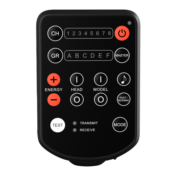
I. Parts (Figure 1-a,Figure 1-b) (Figure 1-a) 1. Channel Indicators (1-8) 2. Channel Button 3. Group Indicators (A-F) 4. Group Button 5. Head Control Buttons (<I> Turn on, <O> Turn off) 6. Energy Adjustment Buttons (<+> Increase, < - > Decrease) 7. - Page 10 Test Button Power Button 10. Command Indicator 11. Master Button 12. Model Control Buttons (<I> Turn on, <O> Turn off) 13. Beeper Button 14. Fast Mode Switch Button (FAST/NORMAL) 15. Mode Adjustment Button 16 17 (Figure 1-b) 16. USB Port 17.
-
Page 11: Getting Started
(Figure 2) Turning E2 on/off 1. Turn on: Press the Power Button [9] to turn on the E2, the Channel Indicator [1] and Group Indicator [3] light up. 2. Turn off: Press and hold the Power Button [9] until all indicators light off. -
Page 12: Connecting To The Camera
3. Lock the E2 by sliding the Mounting Foot Lock Lever [19] to right until the lock lever clicks in place. 4. Turn on the camera and E2 and set the shooting mode of the camera to manual. 5. To detach E2, press the lock-release... - Page 13 In Port [17] of E2. 3. Insert the PC Plug of the flash sync cable into the PC terminal of the camera. * 4. Turn on the camera and E2 and set the shooting mode of the camera to manual. (Figure 4)
-
Page 14: States And Modes
III. States and Modes 1. The followings states and modes are available in E2. 2. Select the appropriate state and mode as described in this manual in actual use. • 13 •... -
Page 15: Basic Functions And Buttons
IV. Basic Functions and Buttons State and Mode Adjustment 1. Press the Mode Adjustment Button [15] to set the E2 to Transmit Mode or Receive Mode. Mode Indicator [7] indicates the selected mode 2. Press and hold the Mode Adjustment... -
Page 16: Group Selection
2. All flash lights that are assigned to the same group under the same channel will be controlled by E2 simultaneously. 3. Press the Group Button [4] to select the group. The Group Indicator [3] corresponding to the selected group (A-F) is illuminated. -
Page 17: Remote Control - Head Control; Model Control; Energy Adjustment
Remote Control – Head Control; Model Control; Energy Adjustment 1. E2 can remotely radio control all flash lights with built-in AODELAN radio system functionality. 2. Both the Channel and Group settings on the E2 unit must match the Channel and Group settings of the flash lights. - Page 18 5. Press the Energy Adjustment Button [6] to increase or decrease the flash output energy. <+> represents increase. < - > represents decrease. Short press Energy Adjustment Button (< 2 seconds) to adjust the flash output energy level in 1/10 f-stop increments.
-
Page 19: Master Mode
E2. 2. At the point E2 will make continuous and short beeps to signal that the command was not executed. 3. The energy of all flash lights in the group will remain unchanged. -
Page 20: Fast/Normal Mode
2. When the E2 is in Receive Mode, press the Test Button [8] to directly release the shutter of the camera connected to E2 (Out Port[18]) or trigger the flash light connected to E2 (Out Port[18]). -
Page 21: Beep
There will be a long beep when pressing the Beeper Button [13] to turn on the beeper. 2. There will be a long beep when E2 is turned on regardless of whether the beeper is turned on or not. -
Page 22: Auto Power Off
Auto Power Off 1. When E2 is turned on, press the Power Button [9] and the Command Indicator [10] blinks one time (lights up for approx. 0.3 seconds), indicating that the Auto Power Off functionality is enabled, the E2 is automatically turned off after 30 minutes of inactivity. -
Page 23: Factory Settings
Factory Settings 1. Ensure that the E2 is turned off. 2. To reset the E2 to factory settings, press and hold down the Fast Mode Switch Button [14] and then press the Power Button [9] simultaneously, E2 is turned on and reset to factory settings. -
Page 24: Operating Instructions
Before starting all of the following operations, please turn off E2 as well as the camera and flash lights which work with E2, and turn on all units after the connection is completed. Unless Relay State is specially mentioned;... -
Page 25: Remote Flash Synchronization
1. Synchronize and remotely control the flash lights with built-in AODELAN radio system. (Figure 5) (Figure 5) Connect the E2 to the camera. (Via hot shoe or flash sync cable.) Set the flash lights to synchronization via radio. - Page 26 Set the E2 and the flash lights to the same radio channel. Select the same group settings for all flash heads that shall be controlled simultaneously. Set the Group of E2 to the same as the group setting for the flash heads to be controlled, or select all groups on E2.
- Page 27 2. Synchronize the flash light without built-in AODELAN radio system. (Figure 6) (Figure 6) Two E2 units are required – E2 (a) and E2 (b). Set E2 (a) to Transmit Mode (Mode Indicator [7] <TRANSMIT> blinks green) and connect it to the camera (via hot shoe or flash sync cable).
- Page 28 (or PC terminal depends on the flash light) . * Set E2 (a) and E2 (b) to the same radio channel. Press the Test Button [8] on E2 (a) to verify that the flash light fires as expected.
-
Page 29: Release Of Remote Camera
Release of Remote Camera 3. Using E2 as a wireless shutter release. (Figure 7) (Figure 7) Two E2 units are required – E2 (a) and E2 (b). • 28 •... - Page 30 Indicator [7] <RECEIVE> blinks green), use a camera release cable corresponding to the camera in use to connect the In Port [17] on the E2 to the remote control terminal on the camera.* * For proper connection with the camera or flash light, consult the user manual of the actual camera or flash light at the same time.
- Page 31 Hand hold E2 (a) and set it to Transmit Mode (Mode Indicator [7] <TRANSMIT> blinks green). Set E2 (a) and E2 (b) to the same radio channel. Press and hold down the Test Button [8] on the handheld E2 (a) until the camera is released.
- Page 32 4. Using E2 as a wired shutter release. (Figure 8) (Figure 8) Under the same situation as in Section 3, press and hold down the Test Button [8] on the E2(b) can also release the camera directly, to use one single E2 as a wired shutter release。***...
-
Page 33: Relay
Relay 5. Relay (to work with the flash lights with built-in AODELAN radio system). (Figure 9) (Figure 9) Two E2 units are required – E2 (a) and E2 (b). • 32 •... - Page 34 Attach E2 (b) to the camera’s hot shoe mount. (A flash sync cable can also be used to connect the In Port [17] on the E2 (b) to the PC terminal on the camera instead of hot shoe connection.) Use a camera release cable...
- Page 35 Set the flash light to synchronization via radio and select the same radio channel as on E2 (b). Hand hold E2 (a) and set it to Relay State Transmit Mode (Mode Indicator [7] <TRANSMIT> blinks red) and select the same radio channel as on E2 (b).
- Page 36 6. Relay (to work with the flash light without built-in AODELAN radio system). (Figure 10) • 35 •...
- Page 37 (Figure 10) • 36 •...
- Page 38 Three E2 units are required – E2 (a), E2 (b) and E2 (c). Attach E2 (b) to the camera’s hot shoe mount. (A flash sync cable can also be used to connect the In Port [17] on the E2 (b) to the PC terminal on the camera instead of hot shoe connection.)
- Page 39 Mode (Mode Indicator [7] <RECEIVE> blinks red) and select a radio channel. Use a flash sync cable to connect the Out Port [18] on the E2 (c) to the flash light’s sync input socket (or PC terminal depends on the flash light). * Set the E2 (c) to Standard State...
- Page 40 Hand hold E2 (a) and set it to Relay State Transmit Mode (Mode Indicator [7] <TRANSMIT> blinks red) and select the same radio channel as on E2 (b). Press and hold down the Test Button [8] on the handheld E2 (a), E2 (b) will release the camera’s shutter to take...
-
Page 41: Specification
VI. Specifications Indicators Mode Indicators [7] State and Mode of the E2 Standard State <TRANSMIT> blinks in green Normal Transmit Mode Standard State <RECEIVE> blinks in green Normal Receive Mode <TRANSMIT> rapidly blinks in Standard State green Fast Transmit Mode Relay State <TRANSMIT>... - Page 42 Notes “Blinks” means blinks once per second. “Rapidly blinks” means blinks three times per second. When the battery is low, the three indicators – Command Indicator [10], Channel Indicator [1] and Group Indicator [3] will rapidly blink at the same time, please replace the batteries with new ones.
- Page 43 Frequency: 2.4 GHz Range: Up to 200m (656ft) Channel: 8 channels (1-8) Group: 6 groups (A-F) and fire all groups function (Master mode) Power: 2 x AAA batteries Max. Sync speed: 1/250 sec**** Sync delay, Fast/Normal mode: 136us /460us Antenna: Internal antenna Interface: Hot shoe mounting foot x 1 3.5mm in port x 1 3.5mm out port x 1...
- Page 44 Accessory: Flash Sync Cable (3.5mm – 3.5mm plug) x 1 Strap x 1 Dimensions: Approx. 91 x 57 x 37mm (3.6 x 2.2 x 1.2 in) Weight: Approx. 72g (2.5 oz) (without batteries) Specifications and design are subject to change without notice. •...
- Page 45 感谢您购买奥德兰产品。 AODELAN E2 是一款兼容 AODELAN 无线 电系统的收发一体机,使用它可以实现闪光 灯与照相机的无线同步并远程控制任意一款 内置 AODELAN 无线电系统的闪光灯,包括 闪光功率控制和造型灯控制。E2 还具备同频 道中继功能,是触发远程照相机与远程闪光 灯同步的最佳方案。 使用前,请阅读本使用说明书以及与 E2 搭 配使用的照相机和闪光灯随附的使用说明书。 • 44 •...
- Page 46 安全须知 请在使用前仔细阅读“安全须知”,并以正 确的方法使用。 请勿试图自行拆开或进行维修。 请勿在有可能起火、爆炸的场所使用本产 品。 本产品不具备防水特性,请远离雨、雪等 高湿度的场合。 请勿将产品放置在超过 45℃的高温环境 下,比如汽车尾箱内。 请勿使用有机溶剂或含酒精的液体来清洁 该产品。 成年人需要在儿童使用本产品时详细说明 如何使用本产品,并在儿童的使用过程中 进行监督。 有关电池的妥善处理和回收,请咨询地方 当局。 • 45 •...
- Page 47 目录 一、 部件 ……………………………… 二、 使用前准备 ……………………… ……………………… 装入电池 …………………… 开启 / 关闭 E2 ……………………… 与相机连接 三、状态及模式 ……………………… 四、 基本功能及按钮 ………………… …………………… 状态模式调节 ………………………… 频道选择 ………………………… 组别选择 遥控 – 灯头控制;造型灯控制; ………………………… 能量调节 ………………………… 主控模式 ………………………… 命令确认 ………………………… 测试功能 ………………… 快速 / 普通模式...
- Page 48 ……………………… 蜂鸣提示音 ………………………… 自动关机 ………………………… 出厂设置 五、操作说明 ………………………… …………………… 遥控闪光同步 ………………… 释放遥控照相机 ………………………… 触发中继 六、规格 ……………………………… • 47 •...
- Page 49 一、部件 (图一 -a, 图一 -b) (图一 -a) 频道指示灯(1-8) 频道按钮 组别指示灯(A-F) 组别按钮 灯头控制按钮 (<I> 打开,<O> 关闭) 能量调节按钮 (<+> 增加,<-> 降低) 模式指示灯 (<TRANSMIT> 发射, <RECEIVE> 接收) • 48 •...
- Page 50 测试按钮 电源按钮 10. 命令指示灯 11. 主控按钮 12. 造型灯控制按钮 (<I> 打开,<O> 关闭) 13. 蜂鸣器按钮 14. 快速模式切换按钮 (<FAST> 快速 /<NORMAL> 普通) 15. 模式调节按钮 16 17 (图一 -b) 16. USB 端口 17. 输入端口(3.5mm) 18. 输出端口(3.5mm) 19. 固定座锁定杆 20. 热靴固定座 • 49 •...
-
Page 51: 开启 / 关闭 E2
二、使用前准备 装入电池 (图二) 1. 打开 E2 后部的电池盖。 2. 按照电池仓中的图示方向装入 2 节 AAA 电池。 3. 盖上电池盖。 (图二) 开启 / 关闭 E2 1. 开启:短按电源按钮 [9] 以开启 E2,频道 指示灯 [1] 和组别指示灯 [3] 亮起。 2. 关闭:长按电源按钮 [9] 直至所有指示灯 熄灭。 • 50 •... - Page 52 与照相机连接 通过热靴 (图三) 1. 关闭 E2 和照相机。 2. 将 E2 的热靴固定座 [20] 插入照相机的热 靴座。 3. 滑动固定座锁定杆 [19] 到右侧直至发出 咔哒声将 E2 锁定到位。 4. 开启照相机和 E2,并将照相机的拍摄模 式设置为手动。 5. 若要取出 E2,按住固定座锁定杆 [19] 上 的释放按钮的同时将锁定杆滑到最左侧, 然后将 E2 滑出照相机的热靴座。 (图三) • 51 •...
- Page 53 通过闪光同步线 (3.5mm – PC, 单独出售) (图四) 1. 关闭 E2 和照相机。 2. 将闪光同步线的 3.5mm 插头插入 E2 的 输入端口 [17]。 3. 将闪光同步线的 PC 插头插入照相机的 PC 端子。* 4. 开启照相机和 E2,并将照相机的拍摄模 式设置为手动。 (图四) * 为了与照相机或闪光灯可以正确连接,请同时参阅 实际照相机或闪光灯的使用说明书。 • 52 •...
- Page 54 三、状态及模式 1. E2 有以下状态及模式可用。 2. 在实际使用中,请按照该说明书中的介绍 选择合适的状态及模式。 • 53 •...
-
Page 55: 频道选择
四、基本功能及按钮 状态模式调节 1. 按模式调节按钮 [15] 将 E2 设定为发射模 式或接收模式。 模式指示灯 [7] 显示所选择的模式。 <TRANSMIT> 表示发射模式。 <RECEIVE> 表示接收模式。 2. 长按模式调节按钮 [15] 5 秒可进入中继状 态或退出回到标准状态。 标准状态下,模式指示灯 [7] 闪绿色。 中继状态下,模式指示灯 [7] 闪红色; 中继状态下不能使用快速模式 <Fast>。 频道选择 频道选择功能允许用户在 2.4GHz 波段... -
Page 56: 能量调节
2. 同频道下被设定为同组别的所有闪光灯接 受 E2 的同步控制。 3. 按组别按钮 [4] 选择组别。 被选中的组别(A-F)所对应的指示灯 [3] 亮起。 4. 按下主控按钮 [11],则所有组别被选定, 接受遥控命令。 组别指示灯(A-F)[3] 全部亮起 遥控 – 灯头控制 ; 造型灯控制 ; 能量调节 1. E2 可对所有内置 AODELAN 无线电系统 的闪光灯进行无线电遥控。 2. 闪光灯上的频道和组别设定必须与 E2 的 频道和组别设定一致。 • 55 •... - Page 57 3. 按灯头控制按钮 [5] 将闪光灯打开或者关 闭。 <I> 表示打开。 <O> 表示关闭。 当 E2 处于接收模式,按下灯头控 制按钮 [5]<O> 会使模式指示灯 [7]<RECEIVE> 一直亮起,表示 E2 已 关闭其接收功能。 4. 按造型灯控制按钮 [12] 将造型灯打开或 者关闭 <I> 表示打开。 <O> 表示关闭。 5. 按能量调节按钮 [6] 将闪光输出能量调高 或者调低。 <+> 表示调高。...
-
Page 58: 主控模式
如果分组中任何闪光灯的输出能量已 经达到最大值或最小值,则其所有输 出能量将保持不变。** 主控模式 1. 在主控模式下,所选频道下的所有组别接 受相同的遥控命令。 2. 按下主控按钮 [11],则所有组别被选定, 接受遥控命令。 命令确认 1. 如果一个闪光灯的输出能量已经被设置为 最大或最小水平,那么该闪光灯无法继续 按照 E2 的命令调高或调低其输出能量。 2. 此时 E2 将发出连续的短促蜂鸣声提示音, 提示功率调节命令未被执行。 3. 分组中闪光灯的输出功率将保持不变。 ** 请参考命令确认部分。 • 57 •... -
Page 59: 测试功能
测试功能 1. E2 处于发射模式时,按测试按钮 [8] 可以 手动发射同步信号,用于遥控释放照相机 快门或者触发闪光以检验功能是否正常。 2. E2 处于接收模式时,按测试按钮 [8] 可 以直接释放与之连接(输出端口 [18])的 照相机快门或者触发与之连接(输出端口 [18])的闪光灯。 快速 / 普通模式 1. E2 的同步触发信号发送延迟时间非常短。 在快速模式下,延迟时间更短。 2. 由于快速模式的耗电量较大,所以只建议 在使用高速快门的情况下使用。 3. 长按 2 秒快速模式切换按钮 [14] 可进入 快速模式或退出回到普通模式。 快速模式下,模式指示灯 [7] <TRANSMIT> 快速闪烁绿色。 4. 快速模式只在标准状态的发射模式下可... -
Page 60: 蜂鸣提示音
蜂鸣提示音 1. 按蜂鸣器按钮 [13] 可以开启或关闭 E2 的 按键提示音。 按蜂鸣器按钮 [13] 关闭蜂鸣器时没有 提示音。 按蜂鸣器按钮 [13] 开启蜂鸣器时会有 长蜂鸣提示音。 2. 不管蜂鸣器是否开启,E2 在开机时都会 有长蜂鸣提示音。 3. 有些功能在特定模式下不被支持,此时即 便蜂鸣器处于开启状态,按下相应按钮也 不会有提示音。例如处于接收模式的 E2 不支持功率调节、造型灯控制等功能,此 时按这些按钮也就没有蜂鸣提示音。 • 59 •... -
Page 61: 自动关机
功能,E2 将会在 30 分钟无操作后自动关 机。 2. 当 E2 处于开机状态时,按一下电源按钮 [9],如果命令指示灯 [10] 亮起约 2 秒, 则表示已停用自动关机功能,E2 将会一 直处于开机状态直至电池耗尽。 出厂设置 1. 确保 E2 已关机。 2. 若要将 E2 复位为出厂设置,按住快速模 式切换按钮 [14] 然后同时按一下电源按 钮 [9],E2 开机并恢复出厂设置。 3. E2 的出厂设置为 – 标准状态普通发射模 式,1 频道,A 组。 • 60 •... - Page 62 五、操作说明 使用注意事项 在开始以下的所有操作之前,请关闭 E2 以及和 E2 搭配使用的照相机和闪光灯的 电源,待完成连接后再开启所有装置。 除非有特别说明为中继状态;否则以下操 作均默认为 E2 处于标准状态下的普通发 射模式或接收模式,模式指示灯 [7] 闪烁 绿色。 E2 标准包装只配备一条闪光同步线 (3.5mm – 3.5mm 插头 );以下操作中所 涉及到的其他线材都是单独出售。 • 61 •...
-
Page 63: 遥控闪光同步
遥控闪光同步 1. 同步触发并遥控有内置 AODELAN 无线电 系统的闪光灯。(图五) (图五) 将 E2 与照相机连接好。(通过热靴或 者闪光同步线。) 设置闪光灯通过无线电同步。 • 62 •... - Page 64 对于应当同时控制的所有灯头选择相 同的组别设置。 在 E2 上将组别设置为欲控制的灯头组 或者选择所有组别。 按下 E2 上的测试按钮 [8],检验灯头 是否可提供正常闪光。 通过按 E2 上的灯头控制按钮 [5] 打开 / 关闭所选组别中的所有灯头。 通过按 E2 上的造灯控制按钮 [12] 打 开 / 关闭所选组别中的所有造型灯。 通过按 E2 上的功率调节按钮 [6] 调高 / 调低所选组别中的输出功率。 • 63 •...
- Page 65 2. 同步触发无内置 AODELAN 无线电系统的 闪光灯。(图六) (图六) 需使用两台 E2 装置 - E2(a) 和 E2(b)。 将 E2(a) 设置为发射模式(模式指示灯 [7]<TRANSMIT> 闪烁绿色)并安装 在照相机上(通过热靴或者闪光同步 线)。 • 64 •...
- Page 66 将 E2(b) 设置为接收模式(模式指示 灯 [7]<RECEIVE> 闪烁绿色)并使用 一条闪光同步线将其输出端口 [18] 与 闪光灯上的同步输入插口 (或 PC 插口, 根据闪光灯而定)进行连接。* 将 E2(a) 和 E2(b) 设置为相同的无线电 频道。 按下 E2(a) 上的测试按钮 [8],检验闪 光灯是否可提供正常闪光。 搭配无内置 AODELAN 无线电系统的 闪光灯使用时,仅支持同步触发功能。 * 为了与照相机或闪光灯可以正确连接,请同时参阅 实际照相机或闪光灯的使用说明书。 • 65 •...
-
Page 67: 释放遥控照相机
释放遥控照相机 3. 将 E2 作为无线快门遥控器来使用。 (图七) (图七) 需使用两台 E2 装置 - E2(a) 和 E2(b)。 • 66 •... - Page 68 将 E2(b) 设置为接收模式(模式指示 灯 [7]<RECEIVE> 闪烁绿色)并使用 配套的快门连接线将其输入端口 [17] 与照相机上的遥控端子进行连接。* 手持 E2(a) 并将其设置为发射模式(模 式指示灯 [7]<TRANSMIT> 闪烁绿 色)。 将 E2(a) 和 E2(b) 设置为相同的无线电 频道。 长按手持 E2(a) 上的测试按钮 [8],直 至照相机快门被释放。*** * 为了与照相机或闪光灯可以正确连接,请同时参阅 实际照相机或闪光灯的使用说明书。 *** 单拍时,将照相机设置为单拍模式。若将照相机 设置为连拍模式,则只要按住测试按钮 [8],照相机 就会一直连拍;由于滞后效应,在放开测试按钮 [8] 后,照相机可能还会再连拍数次。对于连续模式建...
- Page 69 4. 将 E2 作为有线快门遥控器来使用。 (图八) (图八) 在与章节 3 相同的情况下,手持 E2(b) 并长按其上面的测试按钮 [8],也可直 接释放照相机的快门,将单个 E2 作为 有线快门遥控器使用。*** *** 单拍时,将照相机设置为单拍模式。若将照相机 设置为连拍模式,则只要按住测试按钮 [8],照相机 就会一直连拍;由于滞后效应,在放开测试按钮 [8] 后,照相机可能还会再连拍数次。对于连续模式建 议使用 2 fps 或更快的速度拍摄。 • 68 •...
- Page 70 触发中继 5. 触发中继 (搭配有内置 AODELAN 无线 电系统的闪光灯)。(图九) • 69 •...
- Page 71 (图九) 需使用两台 E2 装置 - E2(a) 和 E2(b)。 将 E2(b) 安装到照相机的热靴座上。 (也可通过闪光同步线将 E2(b) 上的 • 70 •...
- Page 72 端子。* 设置 E2(b) 为中继状态接收模式(模 式指示灯 [7]<RECEIVE> 闪烁红色) , 并选择一个无线电频道。 设置闪光灯通过无线电同步并选择与 E2(b) 相同的无线电频道。 手持 E2(a) 并将其设置为中继状态发射 模式(模式指示灯 [7]<TRANSMIT> 闪烁红色),并选择与 E2(b) 相同的 无线电频道。 长按手持 E2(a) 上的测试按钮 [8], E2(b) 将会释放照相机快门进行拍照, 同时 E2(b) 还将同步触发闪光灯闪光。 * 为了与照相机或闪光灯可以正确连接,请同时参阅 实际照相机或闪光灯的使用说明书。 • 71 •...
- Page 73 6. 触发中继(搭配无内置 AODELAN 无线电 系统的闪光灯)。(图十) (图十) 需使用三台 E2 装置 - E2(a)、E2(b) 和 E2(c)。 • 72 •...
- Page 74 将 E2(b) 安装到照相机的热靴座上。 (也可通过闪光同步线将 E2(b) 上的 输入端口 [17] 与照相机上的 PC 端子 进行连接替代热靴连接。) 使用配套的快门连接线将 E2(b) 上的 输出端口 [18] 连接至照相机上的遥控 端子。* 设置 E2(b) 为中继状态接收模式(模 式指示灯 [7]<RECEIVE> 闪烁红色) , 并选择一个无线电频道。 使用闪光同步线将 E2(c) 上的输出端 口 [18] 与闪光灯上的同步输入插口 (或 PC 插口,根据闪光灯而定)进行...
- Page 75 手持 E2(a) 并将其设置为中继状态发射 模式 (模式指示灯 [7]<TRASMIT> 闪 烁红色),并选择与 E2(b) 相同的无 线电频道。 长按手持 E2(a) 上的测试按钮 [8], E2(b) 将会释放照相机快门进行拍照, 同时 E2(b) 还将同步触发 E2(c) 进而触 发闪光灯闪光。 注意:必须将 E2(c) 设置为标准状态接 收模式。如果 E2(c) 也被设置为中继 状态接收模式,E2(a) 将直接同时触发 E2(b) 和 E2(c),闪光灯将无法在照相 机拍照时同步闪光,也就无法实现中 继功能。 • 74 •...
-
Page 76: 触发中继
六、规格 指示灯 模式指示灯 [7] E2 的状态及模式 <TRANSMIT> 闪烁绿色 标准状态普通发射模式 <RECEIVE> 闪烁绿色 标准状态普通接收模式 <TRANSMIT> 快速闪烁绿色 标准状态快速发射模式 <TRANSMIT> 闪烁红色 中继状态普通发射模式 <RECEIVE> 闪烁红色 中继状态普通接收模式 <RECEIVE> 常亮绿色 (或者红色) 接收功能已关闭 命令示灯 [10] E2 状态 点亮约 0.3 秒 发射或接收到一次命令 快速闪烁 电量低 注意 “闪烁” 指每秒闪一次。 “快速闪烁” 指每秒闪三次。... - Page 77 频率:2.4GHz 工作范围:最大 200m 频道:8 个频道 (1-8) 组别:6 个组别 (A-F) 以及全组别触发功能 (主控模式) 电源:2 x AAA 电池 最快同步速度:1/250s**** 同步延迟,快速 / 普通模式: 136us/460us 天线:内置天线 接口:热靴固定座 x 1 3.5mm 输入端口 x 1 3.5mm 输出端口 x 1 Micro-USB B 端口 x 1 配件:闪光同步线 (3.5mm – 3.5mm 插头 ) 1 条...
- Page 78 深圳市奥德兰科技有限公司 Shenzhen Aodelan Technology Co , Ltd. Printed in China...
Need help?
Do you have a question about the E2 and is the answer not in the manual?
Questions and answers