Table of Contents
Advertisement
Disclaimer
The information in this document is subject to change without notice. The
manufacturer makes no representations or warranties with respect to the contents
hereof and specifically disclaims any implied warranties of merchantability or
fitness for any particular purpose. The manufacturer reserves the right to revise this
publication and to make changes from time to time in the content hereof without
obligation of the manufacturer to notify any person of such revision or changes.
Federal Communications Commission (FCC)
This equipment has been tested and found to comply with the limits for a Class B
digital device, pursuant to Part 15 of the FCC Rules. These limits are designed to
provide reasonable protection against harmful interference in a residential
installation. This equipment generates, uses, and can radiate radio frequency
energy and, if not installed and used in accordance with the instructions, may cause
harmful interference to radio communications. However, there is no guarantee that
interference will not occur in a particular installation. If this equipment does cause
harmful interference to radio or television reception, which can be determined by
turning the equipment off and on, the user is encouraged to try to correct the
interference by one or more of the following measures:
•
Reorient or relocate the receiving antenna
•
Increase the separation between the equipment and the receiver
•
Connect the equipment onto an outlet on a circuit different from that to
which the receiver is connected
Consult the dealer or an experienced radio/TV technician for help
•
Shielded interconnect cables and a shielded AC power cable must be employed with
this equipment to ensure compliance with the pertinent RF emission limits
governing this device. Changes or modifications not expressly approved by the
system's manufacturer could void the user's authority to operate the equipment.
Declaration of Conformity
This device complies with part 15 of the FCC rules. Operation is subject to the follow-
ing conditions:
This device may not cause harmful interference.
•
This device must accept any interference received, including interference
•
that may cause undesired operation.
This device is in conformity with the following EC/EMC directives:
Electromagnetic compatibility of multimedia equipment - Emission
EN 55032
requirements
Electromagnetic Compatibility(EMC)
EN 61000-3-2
Part 3-2: Limits-Limits for harmonic current emissions (equipment input
current 16A per phase)
Electromagnetic Compatibility(EMC)
EN 61000-3-3
Part 3-3: Limits-Limitation of voltage changes, voltage fluctuations and flicker
in public low-voltage supply systems, for equipment with rated current 16A
per phase and not subject to conditional connection
Information technology equipment-Immunity characteristics-Limits and
EN 55024
methods of measurement
Safety for information technology equipment including electrical business
EN 60950
equipment
CE marking
GLKD-I2 USER MANUAL
Advertisement
Table of Contents

Related Manuals for ECS GLKD-I2

Summary of Contents for ECS GLKD-I2
- Page 1 16A per phase and not subject to conditional connection Information technology equipment-Immunity characteristics-Limits and EN 55024 methods of measurement Safety for information technology equipment including electrical business EN 60950 equipment CE marking GLKD-I2 USER MANUAL...
-
Page 2: Table Of Contents
TABLE OF CONTENTS Preface Brief Introduction Specifications..................1 Motherboard Components..............3 Header Pin Definition and Jumper Settings.........5 I/O Ports....................7 Multi-language Quick Installation Guide English....................9 Simplified Chinese................11 Korean......................13 Indonesian.....................15 Japanese....................17 Vietnamese..................19 GLKD-I2 USER MANUAL... -
Page 3: Brief Introduction
1 x Front Panel audio header • 1 x Clear CMOS jumper • 1 x Case open header • 1 x Printer header Note: VGA port (rear panel I/O) and DP port (rear panel I/O) are alternative options of the motherboard. GLKD-I2 USER MANUAL... - Page 4 - Support PgUp clear CMOS Hotkey (PS2 KB Model only) - Add BIOS parameters and copy to USB Flash Drive Form Factor • Mini ITX Size, 170mm x 170mm QR Code for the complete manual download on ECS website: http://www.ecs.com.tw GLKD-I2 USER MANUAL...
-
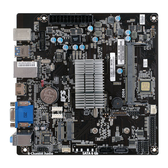
Page 5: Motherboard Components
Motherboard Components GLKD-I2 USER MANUAL... - Page 6 Front panel USB 2.0 headers 13. BAT Battery 14. CLR_CMOS Clear CMOS jumper 15. ATX_POWER Standard 24-pin ATX power connector Note: VGA port(rear panel I/O) and DP port (rear panel I/O) are alternative options of the motherboard. GLKD-I2 USER MANUAL...
-
Page 7: Header Pin Definition And Jumper Settings
Data Set Ready Ground Data Terminal Ready Serial Output Serial Input Data Carrier Detect F_USB1~2 USB Port B (+) USB Port B (-) Ground Power +5V Power +5V USB Port A (-) Ground USB Port A (+) GLKD-I2 USER MANUAL... - Page 8 SLCT Ground Ground BUSK Ground Ground Ground Ground Ground Ground SLCT INIT ERROR STROBE CLR_CMOS Jumper 1-2: NORMAL 2-3: CLEAR CMOS Before clearing the CMOS, make sure to turn off the system. CLR_CMOS GLKD-I2 USER MANUAL...
-
Page 9: I/O Ports
Connect your monitor to the VGA port. 11. DP Port* (optional) You can connect the display device to the display port. Note: VGA port(rear panel I/O) and DP port (rear panel I/O) are alternative options of the motherboard. GLKD-I2 USER MANUAL... - Page 10 Memo GLKD-I2 USER MANUAL...
-
Page 11: Multi-Language Quick Installation Guide
Hardware Installation Guide Installation Steps Step 1. Installation of Memory Modules: 1-1. Align the cutouts on the DIMM 1-2. Insert the memory module to the module edge connector to the notches slot and press it down until it seats in the DIMM slot. correctly. - Page 12 Step 4: Connecting ports on the case: Once the steps above have been completed, please connect the peripherals such as the keyboard, mouse, monitor, etc. Then, connect the power and turn on the system. Please install all the required software. Using BIOS The BIOS (Basic Input and Output System) Setup Utility displays the system’s configuration status and provides you options to set system parameters.
-
Page 13: Simplified Chinese
硬件安装指南 安装步骤 1.安装记忆体模组: 1-1. 将DIMM模块边缘连接器上的切口 1-2. 将内存模块插入插槽和向下按直至 与DIMM插槽中的凹槽对齐。 其正确就位。 确保插槽锁扣紧贴DIMM 模块的边缘。 2-1. 取下机箱后面的I/O挡板,换上主 2-2. 将主板的后I/O对准机箱上的I/O挡板孔 板附带的I/O弹片。 位,放入机箱并以螺丝固定。 VGA端口(后置面板I / O)和DP端口(后置面板I / O)是主板上可选的项目。 3.连接电源线与电源接头: a. 将SATA电缆连接至SATA 硬盘 b. 连接24针电源线与电源接头 请注意电源接头与电源线必须完全扣合。... - Page 14 4.连接机箱端口: 当上述安装步骤完成后,请开始安装键盘,鼠标, 显示器等外围设备,然后连接电 源并启 动系统。请安装好所需的软件。 BIOS使用设定 BIOS程序画面会显示系统配置,同时提供操作选项让您设定系统参数。当开机时, BIOS会进行开机自我测试 (POST),请点击 <D EL> 或 F2 进入BIOS程序设定。第一次 开机时,POST画面可能会显示 信息,请进入BIOS选单 并选 择 将BIOS重新设定为默认值 (更换CPU或内存等硬件变更也 可能会出现此信息)。 此说明内容中提供图片或安装方式仅供参考。...
-
Page 15: Korean
하드웨어 설치 가이드 단계별 설치 방법 1단계. 메모리 모듈 설치하기: 1-1. DIMM 모듈 에지 커넥터의 컷 아웃을 1-2. 메모리 모듈을 슬롯에 삽입하고 올바르게 DIMM 슬롯의 노치에 맞 춥니 다. 장착 될 때까지 아래로 누르십시오. 슬롯 래치가 DIMM 모듈의 모서리에 달라 붙지 않도록하십시오. - Page 16 4단계. 케이스의 포트 연결하기: 일단 위의 단계들이 완료되면, 키보드, 마우스, 모니터 등과 같은 주변기기들을 연결 합니다. 그런 후에, 전원을 연결하고 시스템을 켭니다. 모든 필수 소프트웨어를 설치 합니다. BIOS 사용하기 BIOS 셋업 유틸리티 는 시스템의 환경설정 상태를 표시하며 시스템 매개변수를 설정하기 위한 옵션을 제공합니다. 시스템의 전원을 켜면, BIOS는 Power-On Self Test (POST) 루틴을...
-
Page 17: Indonesian
Panduan Pemasangan Perangkat Keras Langkah-Langkah Pemasangan Langkah 1. Pemasangan Modul Memori: 1-2. Masukkan modul memori ke slot dan konektor tepi ke takik di slot DIMM. tekan ke bawah sampai itu kursi dengan benar. modul DIMM. Langkah 2. Pemasangan Motherboard: 2-1. Pasang kembali pelat I/O casing 2-2. - Page 18 Langkah 4. Menyambungkan port pada casing: Setelah langkah-langkah di atas selesai, harap monitor, dll. Lalu sambungkan daya dan nyalakan sistem. Harap pasang semua perangkat lunak yang dibutuhkan. Menggunakan BIOS Utulitas Pengaturan BIOS (Basic Input and Output System) menampilkan status kon gurasi sistem dan memberi Anda opsi untuk mengatur parameter sistem. Test (POST), harap tekan <DEL >...
-
Page 19: Japanese
1-1. DIMMモジュールのエッジコネクタの切り 2-2. メモリモジュールをスロットに挿入し、それ 欠きをDIMMスロットのノッチに合わせます。 が正しく座るまで押し下げます。 スロットのラッ チがDIMMモジュールの端にしっかりとはまっ ていることを確認します。 3-1. ケースの背面I/Oプレートをマザーボ 3-2. I/Oプレートにマザーボードを位置決め ードに付属のI/Oシールドと交換します。 し、ケース内に配置します。ネジでマザーボー ドをケースに固定します。 VGAポート(背面パネル I / O)およびDPポート(背面パネル I / O)は代替ですマ ザーボードのオプション。 a. IDEハードドライブにIDEケーブルを接 b. 24ピン電源ケーブルを接続します 続します 24ピン電源ケーブルを接続するとき、電源 ケーブルのラッチとATXコネクタが適合す ることを確認してください。... - Page 20 背面パネルは図と異なる場合があります。マザーボードによって異なります。 上記の手順を完了した後、キーボードやマウスなどの周辺機器を接続してください。その後電源 を接続し、システムを起動します。必要なソフトウェアをすべてインストールしてください。周 辺機器をすべてインストールしてください。 BIOS(基本入出力システム)セットアップユーティリティはシステムの構成状態を表示し、 システムパラメータ設定のオプションを提供します。システムを起動すると、BIOSが POSTという診断テストのルーチンを実行します。セットアップを開始するには<DEL>ま たはF2を押してください。初めて電源を投入したとき、POST画面に「CMOS Set- tings Wrong」(CMOSの設定が正しくありません)というメッセージが表示され ることがあります。BIOSに入って「Load Default Settings」(デフォ ルトの設定を読み込み)を選択し、デフォルトのCMOS値をリセットしてください。(別の CPU、メモリなどのシステムハードウェアへの変更でもこのメッセージが表示されることがあ ります。) 詳細な製品仕様については仕様説明書を参照するか、ECSウェブサイトの製品マニ ュアルで詳細な内容をダウンロードしてください。...
-
Page 21: Vietnamese
2-1.
Need help?
Do you have a question about the GLKD-I2 and is the answer not in the manual?
Questions and answers