
Summary of Contents for ZMDI ZSSC5101
- Page 1 Evaluation Kit Description Rev. 1.00 / April 2015 ZSSC5101 xMR Sensor Signal Conditioner Multi-Market Sensing Platforms Precise and Deliberate...
-
Page 2: Table Of Contents
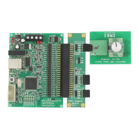
ZMDI’s ZSSC5101 SSC Evaluation Kit, consisting of the SSC Communication Board (SSC CB), the ZSSC5101 Adapter Board (SSC EB), the ZSSC5101 AMR Demo Board, and the calibration software, is designed for sensor module evaluation, laboratory setup, and module calibration development only. - Page 3 Figure 3.2 Updating the Driver for the Communication Board (FT232R USB UART under Device Manager) ... 9 Figure 3.3 Location of the FTDI Driver in the ZSSC5101 Evaluation Software Directory ........9 Figure 3.4 Confirmation Message after Installing FTDI Driver................10 Figure 3.5...
- Page 4 ZSSC5101 Evaluation Kit Description Figure 4.20 Location of Default File ........................24 Figure 4.21 Diagnostics Mode Flag ........................24 For more information, contact ZMDI via PRODUCT@ZMDI.COM. © 2015 Zentrum Mikroelektronik Dresden AG — Rev. 1.00 Kit Description 4 of 25 All rights reserved.
-
Page 5: Introduction
Evaluation Kit Description Introduction The ZSSC5101 Evaluation Kit enables evaluation of the ZSSC5101 xMR Sensor Signal Conditioner IC, which is designed for interfacing with magnetoresistive position sensors. The ZSSC5101 AMR Demo Board included in the kit provides a typical anisotropic magnetoresistive (AMR) position sensor for demonstrating typical calibration procedures and reading example measurement results. -
Page 6: Downloading The Evaluation Kit Software
1.2. Downloading the Evaluation Kit Software To ensure use of the latest version ZSSC5101 Evaluation Software, the software must be downloaded as a zip file from the ZSSC5101 product web page at www.zmdi.com/zssc5101. Alternately, the software can be requested through the ZMDI application support team (see page 25 for contact information). -
Page 7: Hardware Setup
USB cable from the connector on the SSC CB to an available USB port on the user’s computer. Note that up to two ZSSC5101 AMR Demo Boards can be connected at the same time (via the Module 1 and Module 2 connectors on the ZSSC5101 Adaptor Board). -
Page 8: Software Setup
The SSC Communication Board converts the USB bus protocol to a serial data interface for communication between the user’s computer and the ZSSC5101. A special driver (FTDI) must be installed. Before continuing, ensure that the ZSSC5101 Evaluation Kit is connected via a USB cable to the user’s computer as described in section 2. -
Page 9: Figure 3.2 Updating The Driver For The Communication Board (Ft232R Usb Uart Under Device Manager)
Figure 3.2 Updating the Driver for the Communication Board (FT232R USB UART under Device Manager) 5. Next, select the option to manually browse for a driver: 6. Navigate to the UsbDriver subdirectory under the user-selected directory for the downloaded ZSSC5101 Evaluation Software. Select the CDM…..-Certified subdirectory as shown in Figure 3.3. Click the “OK”... -
Page 10: Starting The Zssc5101 Evaluation Software
The software provides a graphical user interface (GUI) for communi- cation and programming of the ZSSC5101. To start the GUI, go to the ZSSC5101_GUI subdirectory and click on the ZSSC5101_GUI.exe file to run the software. -
Page 11: Using The Zssc5101 Evaluation Software
“About” on the top main menu (see Figure 4.1). “Setup” Tab 4.2. The initial screen for the ZSSC5101 Evaluation Software (i.e., the GUI) is the “Setup” tab as shown in Figure 4.1. Figure 4.1 “Setup” Tab © 2015 Zentrum Mikroelektronik Dresden AG — Rev. 1.00... -
Page 12: Figure 4.2 "Setup" Tab Example With Module 1 Selected
Under “Angle range,” select whether the ZSSC5101 chip is interfacing with an AMR or GMR/TMR sensor signal. For the ZSSC5101 AMR Demo Board V1.0, which is included in the kit, choose “180° (AMR).” Next, click the “Connect” button (see Figure 4.1). The gray “Connection status” button changes to “Connected”... -
Page 13: Adc And Offset Calibration" Tab
ZSSC5101 Evaluation Kit Description “ADC and Offset Calibration” Tab 4.3. The “ADC and Offset calibration” tab is used to calibrate the offset of the sensor and perform an estimation of the resulting error. Figure 4.3 “ADC and Offset Calibration” Screen ©... -
Page 14: Offset Calibration
The software calculates the offset parameters and stores them in place of the default factory settings in the ZSSC5101’s EEPROM. The ZSSC5101 is now calibrated for the offset of the AMR position sensor at room temperature. The same procedure can be repeated under high temperature conditions by selecting the “High temperature”... -
Page 15: Estimating The Resulting Angle Error
ZSSC5101 Evaluation Kit Description 4.3.2. Estimating the Resulting Angle Error The ZSSC51201 Evaluation Kit provides a unique algorithm for Figure 4.5 “Start Calibration Check” estimating the resulting angle error without the need for a precision angle reference. It is only necessary to rotate the magnet after calibration and click the “Start calibration check”... -
Page 16: Angle Calibration" Tab
Figure 4.8 “Read Angle” Screen “Angle Calibration” Tab 4.5. The “Angle Calibration” tab enables setting the ZSSC5101 to match the mechanical angle limits of the application to which it is connected (e.g., a pedal). © 2015 Zentrum Mikroelektronik Dresden AG — Rev. 1.00... -
Page 17: Setting The Angle Range Limits And Switch Angle
ZSSC5101 Evaluation Kit Description To utilize the full angle range (e.g., 180° for AMR sensors), click the “Reset to default” button. This programs a linear ramp over the maximum angle range. To perform an angle calibration for both modules sequentially, check the “Module 1+2 angle calibration”... -
Page 18: Figure 4.10 Setting The Angle Range With The "Angle Calibration" Tab
ZSSC5101 Evaluation Kit Description 1. Click the “Start” button on the “Angle Calibration” tab and wait until the “Set Start” button becomes active. 2. Move the magnet to the start position (note that this is the maximum clockwise position when looking at the sensor from the top). -
Page 19: Checking The Calibrated Angle
ZSSC5101 Evaluation Kit Description 4.5.2. Checking the Calibrated Angle Figure 4.12 Angle Calibration Strong Recommendation: Verify the actual angle and output value by Check Example clicking the “Check” button under “Check output” on the “Angle Calibration” tab (see Figure 4.9). The two display fields under “Check output”... -
Page 20: Digital Out" Tab
ZSSC5101 Evaluation Kit Description “Digital Out” Tab 4.7. The “Digital Out” tab displays an XY plot for which the X-axis represents the angle and the Y-axis represents the output value (the ramp). To generate a graph, click the “Read” button and slowly rotate the magnet over the full angle range. -
Page 21: Analog Out" Tab
4.8. The “Analog Out” tab shows the actual analog output voltage of the sensor (the voltage at the ZSSC5101’s VOUT pin). The X-axis of the plot is the time, scrolling from right to left, and the Y-axis is the analog output voltage of the sensor that is measured by an ADC in the microcontroller of the SSC Communication Board. -
Page 22: Figure 4.17 "Analog Out" Screen Example With Two Modules
ZSSC5101 Evaluation Kit Description Figure 4.17 “Analog Out” Screen Example with Two Modules © 2015 Zentrum Mikroelektronik Dresden AG — Rev. 1.00 Kit Description 22 of 25 All rights reserved. The material contained herein may not be reproduced, adapted, merged, translated, stored, or used without the April 17, 2015 prior written consent of the copyright owner. -
Page 23: Memory" Tab
The “Memory” tab is used to read and modify the EEPROM contents for factory settings, user settings, and the control register. For further details about the settings refer to the ZSSC5101 Data Sheet and the ZSSC5101 Application Note – Programming Guidelines. -
Page 24: Loading And Saving Eeprom Settings
File → Load EEPROM. The resulting dialog allows navigating to locate and load the file. Then click the “EEPROM Write” button on the “Memory” tab to load the values in the ZSSC5101. The downloaded software provides an EEPROM configuration file Figure 4.20 Location of Default File... -
Page 25: Related Documents
Related Documents Note: X_xy refers to the current revision of the document. Document File Name ZSSC5101 Data Sheet ZSSC5101_Data_Sheet_Rev_X_xy.pdf ZSSC5101 Application Note – Programming Guidelines* ZSSC5101_AN_Programming_Rev_X_xy.pdf on ZMDI’s website at Visit the ZSSC5101 product page www.zmdi.com/zssc5101 www.zmdi.com or contact your nearest sales office for the latest version of these documents.