Table of Contents
Advertisement
Quick Links
Advertisement
Table of Contents

Summary of Contents for FD TMS
- Page 1 Thermal Gas Mass Flowmeter Installation and Operation Guide...
-
Page 2: Table Of Contents
CONTENTS About this manual ....................- 3 - 2. Safety Information ......................- 4 - 2.1 Use personnel ....................... - 4 - store and handling ....................- 4 - Application condition ................... - 4 - Safety standards and specifications ..............- 4 - Intrinsic safety and explosion protection ............ -
Page 3: About This Manual
Appendix 4 Upper Range Value of Common Gas ............ - 37 - 1. About this manual Thank you for choosing our products. Through this manual, we strive to give you an accurate understanding of the thermal mass flowmeter measurement principle, related concepts, terminology and installation and application of the correct methods and conditions. -
Page 4: Safety Information
2. Safety Information 2.1 Use personnel The thermal mass flowmeter is a precision instrument which is produced by the latest technology and technology. Improper installation and use can lead to abnormal and damage of the instrument and even the process control equipment. Engineers and technicians who install, set up and connect the product must read this manual carefully before using the instrument. -
Page 5: Introduction
Please return to the professional recycling company or send back to us, so as to avoid polluting the environment. 3. Introduction 3.1 measuring principle Thermal gas mass flow meter is designed on the basis of thermal dispersion, and adopts method of constant differential temperature to measuring gas flow. -
Page 6: Specifications
temperature), and the meter adopts method of constant differential temperature, therefore the meter do not need to do temperature and pressure compensation in principle. 3.2 Specifications Features Measuring the mass flow or volume flow of gas Do not need to do temperature and pressure compensation in principle with accurate measurement and easy operation. -
Page 7: Mechanical Construction
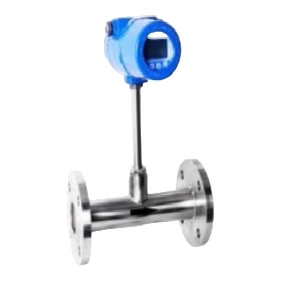
Protection Class IP65 Sensor Housing Stainless steel (316) Material 3.3 Mechanical Construction 3.3.1 Appearance Fig. 1 Standard Insertion Flow Meter Fig. 2 Flanged Flow Meter (Pipe size DN100-DN500) (Pipe size DN10-DN80) Fig. 3 Hot-tapped Insertion Flow Meter (Pipe size DN100-DN4000. Special requirements please contact us) The insertion sensor of compact insertion flow meter should be inserted to axis of pipe, and the length of the insertion sensor is decided by pipe size, please confirm the pipe size when ordering. - Page 8 3.3.2 Dimensions Dimensions of standard insertion sensor Dimensions of hot-tapped insertion sensor The dimensions of flanged sensor PN1.6Mpa Plane and surface plate flat welding steel pipe flanges (Unit: mm) Flange Nominal Center Screw Flange Pipeline Outer Sealing Face Screw Diameter Hole Hole Thickness...
-
Page 9: Wiring
For DN15-DN80, the meter can be made with threading to connect. The above table is used for rated pressure of 1.6MPa. If the rated pressure is more than 1.6MPa, please contact us for special order. 4. Wiring 4.1 Preparation of wiring ... -
Page 10: Terminal Description
4.2 Terminal description Terminal diagram Mark Description AC85V~AC220V L AC85V~AC220V N 24V Power supply positive pole 24V Power supply 0V Pulse output positive pole Pulse output negative pole Current output positive pole Current output negative pole 485+/A RS485 communication interface A 485-/B RS485 communication interface B ALARM1... -
Page 11: Terminal Connection
4.3 Terminal connection Pulse output wiring Analog output wiring - 11 -... -
Page 12: Technical Parameters
5. technical parameters Power Supply Supply Voltage 24VDC/1.5A Allow residual ripple:0~100Hz, Upp = 30Mv,Uss<10mV Maximum noise:500Hz~10KHz ,U = 2.0Mv or 85~265V AC Operating current <650mA Output Output current mode 4~20mA/ Fixed current output RS485 interface Baud rate:1200/2400/4800/9600/19200 Data:8 Check:None/Odd/Even Stop:1 Baud rate:9600 ,Data:8,Check:None ,... -
Page 13: 6.Install
6.Install A stable flow field is the premise of the accurate measurement of the thermal instrument. Therfore, please note following points when installing the instrument. 6.1 Installation direction ●Horizontal installation The process pressure must not exceed 2MPa when installing ●Vertical installation The process pressure must not exceed 2MPa when installing 6.2 Pipe requirements If the Interference sources (i.e. - Page 14 The contorl valves are recommended to be place at rare of instrument. For the light gases, such as helium and hydrogen, front straightway lengths should be doubled. a = front straightway length b = rare straightway lengths Control valves and shut-off valves should be palced at rare of instrument. - 14 -...
-
Page 15: Installation Steps
6.3 Installation Steps The base of thermal flowmeter The base of Hot-tapped insertion type The base of standard insertion type No welding in explosive environment Carry out the welding operation in accordance with the requirements of special environment. When installing, place the base on the top of pipe, and make the through-hole of base be perpendicular to axis of pipe. - Page 16 180° or 270° to meet various requirements. The installation of hot-tapped insertion type Before installation, please conform the connection type and install fittings. Before installation, the site must be shut down, and strictly follow the rules of factory. ...
-
Page 17: 7.Operating The Instrument
7.Operating the instrument 7.1 Keyboard and display Display Keyboard Cancel/Exit Key Shift Key Modify/Page Key Confirm/Enter Key - 17 -... -
Page 18: 7.2 Menu Instruction
7.2 Menu Instruction 7.2.1 Display sreens Display the instant flow rate and Display instant flow Present value of output the unit of instant flow rate. velocity, the unit is fixed as m/s. current. The bar at bottom Cumulative flow and the unit of 0 and 3.1 indicate the range of indicates the percentage of Cumulative flow... - Page 19 7.2.2 Menu selecting and password entering Menu Selecting SET: Setting of basic parameters CLR: Setting the integer and decimal of cumulative flow ImA: Setting the current parameters ALM: Setting the alarm parameters COM: settings of RS485 communication CAL: Calibrate instrument ADJ: Correction flow value SYS: Setting the system parameters QHD: Query history data...
- Page 20 Press Shift Key to select the menu item. To set the basic parameters, move the black background cursor to "SETTINGS" item, press Enter key and the password entering screen appears. Press Enter Key once more, to switch to password entering model (prompted by blinkong cursor).
- Page 21 7.2.3 Basic Paramters Language: Simplified Chinese/English User Zero point and present voltage If there is no medium flow but the isntrument does not display the zero flow rate, adjust the user zero point to make set the display to zero. >...
- Page 22 > signal indicates that this field is adjustable. To switch between lower span and upper span by pressing Shift Key. Press enter to set span limits, the first digit will blink if it in editing model. Damping factor: default value is 2 while it could be adjusted bwtween 0 and 50.
- Page 23 measured value. Sampling period is set as an increamtal of 200ms. For example, if the sampling period is set 5, the actual instrument sampling time is 5*200ms = 1s. Select output pulse or frequency Output pulse width (50-1000ms) Pulse equivalent: Defines how many volum per pulse. There 4 pulse equivalents: 1.0、10.0、100.0 and 1000.0.
- Page 24 measured value. Sampling period is set as an increamtal of 200ms. For example, if the sampling period is set 5, the actual instrument sampling time is 5*200ms = 1s. Select menu item in the menu selection screen then enter the password. - 24 -...
- Page 25 After entered the menu item , press the "ESC" Key to return to the menu selection creen, press the - 25 -...
- Page 26 "ENT" key to enter the value set 7.2.4 Totalizer Settings Clear or set the cumulative flow decimal and integer - 26 -...
- Page 27 7.2.5 Current settings Current output model: 4~20mA and fixed current. When the "Fixed current" is selected, the output currrent is fixed in a given value. For example: the current output model is set to "4~20mA" When there is no flow, if the output is measured as 3.89mA with a multimeter, then set the "...
- Page 28 7.2.7 Communication Settings Communication protocol Protocol: Modbus RTU, other ,HART Modbus Device ID, ranged from 0 to 255 HART Device ID, ranged from 0 to 15 HART Protocol : if Device ID is non-zero value, Analog output fixed to 4mA PV: Flow Velocity Temperature...
- Page 29 7.2.9 Correction Settings Segmental correction factor. Up to 5 segments could be set to correct the nonlinear errors. The segment number must be ascending. The total number of segments could be less than 5 but the correction takes from the firt segment and in a row. correction factor 1.143 =10.00/8.75 correction factor 0.899 =(30.00-10.00)/(31.00-8.75) correction factor 0.952 =(50.00-30.00)/(52.00-31.00)
- Page 30 7.2.10 System paramters Settings System time calibration The type of temperature sensor, temperature sensor is based on the type of hardware, the circuit is determined, no need to modify the sensor model. The interval between the 60 data points, which is the interval between the data of the historical data curve, and the interval between the adjacent data is the interval between the adjacent 2 data.
- Page 31 Select menu item in the menu selection screen then enter the password. 7.2.11 Query history data Enter the value of the date you want to query, the following two lines of traffic value and cumulative value. Daily at 8 am the meter automatically saves the current flow and the fatigue measurement 7.2.12 Self-test Press enter self-test,display √,that is normal;...
-
Page 32: 8. Quality Asurrance And After-Sale Service
8. Quality asurrance and after-sale service According to the ISO9001:2000 quality management and control system, this product is made of new raw materials and components, and has been tested strictly in factory. However, due to the uncertainties that may arise in transportation or use, we undertake to ensure that: ... -
Page 33: Appendix 1 Modbus Register Address Table
Appendix 1 Modbus register address table Floating point data arrangement is F2-F1-F4-F3 (F4-F3-F2-F1 High to low) register address Register name Register data type data format number 4x0001-4x0002 Flow float IEEE754 01 03 00 00 00 02 C4 0B 01 03 04 00 00 00 00 FA 33 4x0003-4x0004 velocity float... -
Page 34: Appendix 2 Conversion Coefficient Of Common Gas
Appendix 2 Conversion Coefficient of Common Gas According to different gas on site, the calibration in lab translates the flow rate of actual gas on site into flow rate of air, and then begins to calibrate the flow rate at present. Therefore, when using the meter on site, the meter displays mass flow or volume flow of actual gas. - Page 35 Hydrogen (H 3.4224 0.0899 1.0040 Hydrogen Bromide (HBr) 0.0861 3.61 0.9940 Hydrogen Chloride (HCI) 0.1911 1.627 0.9940 Hydrogen Fluoride (HF) 0.3482 0.893 0.9940 Hydrogen Iodide (HI) 0.0545 5.707 0.9930 Hydrogen Sulfide (H 0.2278 1.52 0.8390 Helium (He) 1.2418 0.1786 1.4066 Krypton (Kr) 0..0593 3.739...
-
Page 36: Appendix 3 Trouble Shooting
Appendix 3 Trouble Shooting Before any hardware repair, please ensure all following points are correct as these affect the performance 1. Check if the instrument is correctly supplied power 2. Check if the instrument wiring is correct against Charpter 2 3. - Page 37 Appendix 4 Upper Range Value of Common Gas (Unit: Nm /h. The follow table can be extended) Nominal ) ) Diameter Nitrogen(N Oxygen(O Hydrogen(H (mm) 1200 1200 1800 1800 2800 2800 1420 4400 4400 2210 6300 6300 3200 10000 10000 5650 1880 17000...
- Page 38 Qs: The flow rate in standard condition (Nm3/h). Qn: The flow rate in working condition (m3/h). t: The medium temperature in working condition (℃). p: The medium pressure in working condition (Gauge pressure, kPa). - 38 -...
Need help?
Do you have a question about the TMS and is the answer not in the manual?
Questions and answers