Advertisement
Quick Links
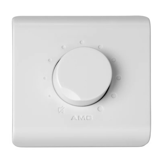
C 5/ C 30/ C 60 volume controls
1
Connect volume controllers according wiring diagrams below. Select requested mode: passive or active .
WIRING DIAGRAM
C 5 volume control for 100 V audio lines
IN
N1
Amp.
+
IN
6
GND
5
GND
4
100V
OUT
3
G
2
_
+24V
1
DG127-6
Speaker
P
Passive mode: C X attenuates the volume if 24 V is not connected to 24 V terminal.
After the voltage supplying, C X sets the maximum volume level.
Active mode: C X set the maximum volume level if 24 V is not connected to 24 V terminal.
A
After the voltage supplying, C X starts attenuate volume.
INSTALLATION MANUAL
C 5/ C 30/ C 60 Volume controls
Switch for active or passive mode selection.
A
P
5.6k
5.6k
5.6k
5.6k
5.6k
RS1
5.6k
4
6
5.6k
3 OUT
K1
5.6k
5
5.6k
7.5k
7.5k
2
1
5.6k
10 k
SW-1*1 1WAY
15 k
SRS-24VDC-SH
22 k
CL1
47 k
100k
104
C 30/ C 60 volume control for 100 V audio lines
IN
N1
Amp.
+
IN
6
GND
5
GND
4
100V
OUT
3
G
2
_
+24V
1
DG127-6
235BYQ
Speaker
Switch for active or passive mode selection.
A
P
RS1
4
6
3 OUT
K1
5
2
1
SW-1*1 1WAY
SRS-24VDC-SH
CL1
104
Advertisement

Summary of Contents for AMC C 5
- Page 1 Connect volume controllers according wiring diagrams below. Select requested mode: passive or active . WIRING DIAGRAM C 5 volume control for 100 V audio lines C 30/ C 60 volume control for 100 V audio lines Switch for active or passive mode selection.
- Page 2 C 5/ C 30/ C 60 volume controls Install ush mount box into the wall. Please note - controllers will t well only with AMC ush mount wall boxes. There are two type of boxes: for drywalls - CBh, for solid walls - CBs. Items can be purchased optionally.
