Advertisement
Quick Links
5330 East 25
Street
th
Indianapolis, Indiana 46218
Phone (317) 261-1212
Fax (317) 261-1208
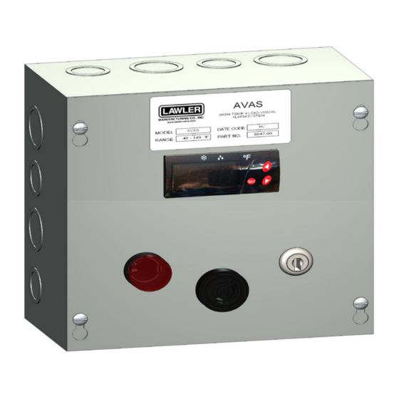
Description
The Audio/Visual Alarm System is designed to give
a visual and audible warning in cases where water
temperature exceeds a pre-programmed setpoint. In
addition, the alarm system can control an optional
solenoid valve, shutting down the flow of water if
necessary. The probe temperature is displayed on
a bright 3-digit LED display, and access to the unit
programming is done thru the password protected
keypad on the front face. A keylock switch is pro-
vided to override the audible alarm.
Specifications
Probe Range: -58 to +302°F
Input: Thermistor (1000Ω @ 25°C)
Accuracy: ±1°
Resolution: ±1 Digit
Supply Voltage: 120 VAC
Ambient Temperature: 32 to +131°F
Storage Temperature: -4 to + 176°F
Display: 3-digit, Red, ½" High
AVAS
Audio/Visual Alarm System
Installation
The Alarm System comes with a standard 120 VAC
pigtail. The controller uses a SPDT relay powering the
horn, and light, as well as an optional normally closed
solenoid valve. Please see Lawler Manufacturing,
Inc. about approved solenoid valves to use with the
alarm system so as not to overload the controller.
Observe proper polarity when connecting to the ter-
minal block on the back panel of the enclosure. The
wiring diagram can be found on page 3.
Upon powering the unit up the solenoid valve will
open allowing the flow of water. If the set point is
exceeded, the valve will close, and the audible and
visual alarms will come on. The audible alarm can
be bypassed with the keylock switch. The unit will
return to normal when the temperature goes below
the sum of the set point and the high alarm minus the
hysteresis.
Parameters
Code Description
SP
Set Point
r0
Hysteresis
r1
Lower Value Set Point
r2
Upper Value Set Point
d0
Heating or Cooling
d2
Time for Defrosting
d8
Interval between Defrost
c0
Min. Stop Time
c1
Continuous Cycle Time
c2
On Time of Fault Cycle
c3
Off Time of Fault Cycle
A0
Alarm differential/hysteresis 1° to 20°
A1
Max alarm temp
A2
Min alarm temp
A7
Alarm time valaidation
P0
Temperature Scale
P1
Ambient Probe Adj.
P4
Decimal Point
H0
Factory Settings
H4
Address
H5
Parameter Access Code
H6
Ambient Probe Type
t0
Max Temp on Display
(1)
Installation &
Maintenance Manual
M AVAS A
Range
Default
r1 to r2
120°F
1 to 20
2°F
-50 to +150°F
-50°
-50 to +302°F
200°F
Ht/Co
Co
0 to 59 Min
0 Min
1 to 24 Hrs
1 Hr
0 to 59 Min Load 0 Min
0 to 24 Hrs
0 Hrs
0 to 999 Min
0 Min
0 to 999 Min
0 Min
5° F
1° to 20°
10° F
1° to 20°
90° F
0 to 99 Min
0 Min
Option
0/F°
-10 to +10°F
0°F
Option
No
Option
0
0 to 999
0
00 to 99
00
Option
PTC
-50 to +302°F
200°F
Advertisement

Summary of Contents for Lawler AVAS
- Page 1 The controller uses a SPDT relay powering the horn, and light, as well as an optional normally closed solenoid valve. Please see Lawler Manufacturing, Inc. about approved solenoid valves to use with the alarm system so as not to overload the controller.
- Page 2 For more information: www.oehha.org/prop65 GUARANTEE We guarantee the Lawler Mixing Valve to be free from held responsible, however, for any labor incidental def ects in workmanship and material, and for a pe- to, or for any damages caused by defective mate- riod of one year from date of purchase, will replace rial.
- Page 3 AVAS Wiring Diagram...
Need help?
Do you have a question about the AVAS and is the answer not in the manual?
Questions and answers