Table of Contents
Advertisement
Quick Links
EMB-OPT02
User Manual
Version 1.0
ⓒ 2005 DAQ SYSTEM Co., Ltd. All rights reserved.
Microsoft® is a registered trademark; Windows®, Windows NT®, Windows XP®, Windows 7®, Windows 8®, Windows 10®
All other trademarks or intellectual property mentioned herein belongs to their respective owners.
Information furnished by DAQ SYSTEM is believed to be accurate and reliable, However, no responsibility is assumed by DAQ SYSTEM for its use, nor
for any infringements of patents or other rights of third parties which may result from its use. No license is granted by implication or otherwise under
any patent or copyrights of DAQ SYSTEM.
The information in this document is subject to change without notice and no part of this document may e copied or reproduced without the prior
written consent.
Advertisement
Table of Contents

Related Manuals for DAQ system EMB-OPT02

Summary of Contents for DAQ system EMB-OPT02
- Page 1 All other trademarks or intellectual property mentioned herein belongs to their respective owners. Information furnished by DAQ SYSTEM is believed to be accurate and reliable, However, no responsibility is assumed by DAQ SYSTEM for its use, nor for any infringements of patents or other rights of third parties which may result from its use. No license is granted by implication or otherwise under any patent or copyrights of DAQ SYSTEM.
-
Page 2: Table Of Contents
EMB-OPT02 User’s Manual Contents 1. EMB-OPT02 Introduction --------------------------------------------------------- 2. EMB-OPT02 Function ------------------------------------------------------------ J1 Connector ----------------------------------------------------------------- 2-2 JP1 Connector --------------------------------------------------------------------- 2-3 SW1 Switch --------------------------------------------------------------------- 2-4 SW3 Switch -------------------------------------------------------------------- CN1(SFP) Connector ---------------------------------------------------------------- 2-7 Fiber Cable -------------------------------------------------------------------- Appendix A-1 Board Size --------------------------------------------------------------- A-2 Repair Regulations... -
Page 3: Emb-Opt02 Introduction
EMB-OPT02 User’s Manual 1. EMB-OPT02 소개 The EMB-OPT02 board converts the parallel (D0..D47) data signal of the J1 connector into an optical signal and outputs it. [Figure 1-1] shows an example of using the EMB-OPT02 board, which converts the image signal from the CameraLink camera into light and transmits it to the PCIe-OPT02 board, which is the light receiving board. - Page 4 EMB-OPT02 User’s Manual Fiber Cable Connection Caution) Be careful not to twist the cable when connecting it to the SFP cage.
-
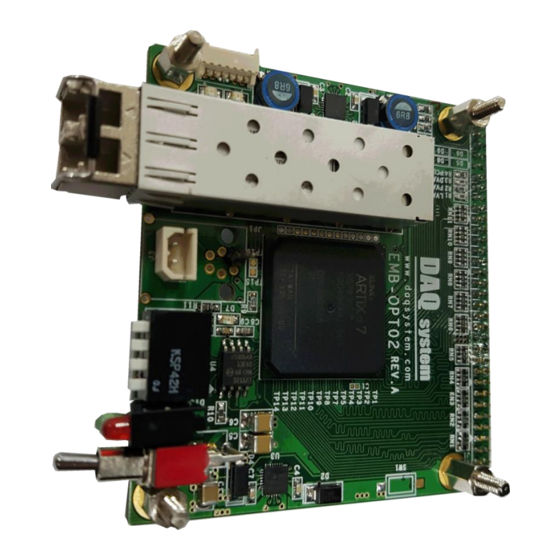
Page 5: Emb-Opt02 Function
EMB-OPT02 User’s Manual 2. EMB-OPT02 Function Each name and function description of EMB-OPT2 is as follows. EMB-OPT02 Board [그림 2-1. EMB-OPT01 Layout] [Table 1. EMB-OPT02 main function description] Name Description Camera Link / DIO_IN0..47 Connector U1, U3 1.2V, 1.8V, 3.3V Output... -
Page 6: J1 Connector
EMB-OPT02 User’s Manual J1 Connector The figure below shows the pin map of the J1 connector. [Figure 2-2. EMB-OPT02 J1 Connector Pin-out] [Table 2. J1 Connector] Name Description Remark 3.3V 3.3V Power 12V Power DIO_IN0 Digital In/Out Data 0 DIO_IN1... - Page 7 EMB-OPT02 User’s Manual DIO_IN24 Digital In/Out 24 DIO_IN25 Digital In/Out 25 DIO_IN26 Digital In/Out 26 DIO_IN27 Digital In/Out 27 DIO_IN28 Digital In/Out 28 DIO_IN29 Digital In/Out 29 DIO_IN30 Digital In/Out 30 DIO_IN31 Digital In/Out 31 DIO_IN32 GPIO00 DIO_IN33 GPIO01 DIO_IN34...
-
Page 8: Jp1 Connector
EMB-OPT02 User’s Manual I2C_SDA I2C Serial Data I2C_SCL I2C Serial Clock JP1 Connector This is an external 12V DC Jack power connector. (HR10-7R-6S-RA) [Figure 2-3. Rated power] SW1 Switch It is an option select switch. SWITCH 3 OFF : Vsync... -
Page 9: Sw3 Switch
2-5 CN1 (SFP) Connector In the case of EMB-OPT02, an SFP (Small Form Factor Pluggable) connector is used as a Fiber-Transmission Transceiver device. The SFP transceiver is designed to support various optical transmissions such as SONET, Gigabit Ethernet, and Fiber Channel. It supports hot-pluggable transceiver and can be connected to network device motherboard with fiber or copper networking cable. - Page 10 EMB-OPT02 User’s Manual [Table 3. CN1 SFP Connector] Name Description Remark VeeT Transmitter Ground TxFault Transmitter Fault TxDisable Transmitter Disable Serial Interface Data Line Serial Interface Clock MOD-ABS Module Absent, connected to VeeT or VeeR Rx Rate Select Open or Low = 2.125 or 4.25 Gb/s Fibre Channel (Low Bandwidth) High = 8.5 Gb/s Fibre Channel (High Bandwidth)
-
Page 11: Fiber Cable
Optical connectors include LC, ST, MTRJ, SC, FC, and MU types, but EMB-OPT02 mainly uses multimode LC type as shown in [Figure 2-7]. - Page 12 EMB-OPT02 User’s Manual (1) Single Mode LC Type (2) Multi Mode LC Type [Figure 2-7. Cable type according to transmission mode]...
-
Page 13: Appendix
EMB-OPT02 User’s Manual Appendix A-1 Board Size The external sizes of the board are as follows. (65 x 69mm) < Top View >... -
Page 14: Repair Regulations
EMB-OPT02 User’s Manual A-2 Repair Regulations Thank you for purchasing a DAQSYSTEM product. Please refer to the following regarding Customer Service regulated by DAQSYSTEM. (1) Read the user manual and follow the instructions before using the DAQSYSTEM product. (2) When returning the product to be repaired, please write down the symptoms of the failure and send it to the head office. - Page 15 EMB-OPT02 User’s Manual MEMO Contact Point Web sit : https://www.daqsystem.com Email : postmaster@daqsystem.com...
Need help?
Do you have a question about the EMB-OPT02 and is the answer not in the manual?
Questions and answers