Table of Contents
Advertisement
Available languages
Available languages
Quick Links
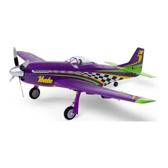
UMX
P-51D
™
Voodoo
Scan the QR code and select the Manuals and Support quick links from
the product page for the most up-to-date manual information.
Scannen Sie den QR-Code und wählen Sie auf der Produktseite
die Quicklinks Handbücher und Unterstützung, um die aktuellsten
Informationen zu Handbücher.
Scannez le code QR et sélectionnez les liens rapides Manuals and Support
sur la page du produit pour obtenir les informations les plus récentes
sur le manuel.
Scannerizzare il codice QR e selezionare i Link veloci Manuali e Supporto
dalla pagina del prodotto per le informazioni manuali più aggiornate.
EFLU4350
Instruction Manual
Bedienungsanleitung
Manuel d'utilisation
Manuale di Istruzioni
Advertisement
Chapters
Table of Contents

Related Manuals for E-FLITE Horizon Hobby UMX Voodoo P-51D

Summary of Contents for E-FLITE Horizon Hobby UMX Voodoo P-51D
- Page 1 P-51D ™ Voodoo Scan the QR code and select the Manuals and Support quick links from the product page for the most up-to-date manual information. Scannen Sie den QR-Code und wählen Sie auf der Produktseite die Quicklinks Handbücher und Unterstützung, um die aktuellsten Informationen zu Handbücher.
- Page 2 NOTICE All instructions, warranties and other collateral documents are subject to change at the sole discretion of Horizon Hobby, LLC. For up-to-date product literature, visit horizonhobby.com or towerhobbies.com and click on the support or resources tab for this product. MEANING OF SPECIAL LANGUAGE The following terms are used throughout the product literature to indicate various levels of potential harm when operating this product: WARNING: Procedures, which if not properly followed, create the probability of property damage, collateral damage,...
-
Page 3: Table Of Contents
Included / Recommended Equipment 19.4 in (493mm) Motor: Installed Brushless Outrunner, 2150Kv, 12-Pole (SPMXAM1208B) Servo: Installed (4) 2.3-Gram Long-Throw Linear Servo (SPMSA2030LO) Receiver: Installed Spektrum AS3X/SAFE Receiver (SPMA3190) ™ Recommended Battery: Required Spektrum 300mAh 3S 11.1V 30C; JST-RCY Li-Po (SPMX3003SJ30) Recommended Battery Charger: Required S155 (SPMXC2050) WITH IC3 to JST-RCY adapter... -
Page 4: Low Voltage Cutoff (Lvc)
Low Voltage Cutoff (LVC) When a Li-Po battery is discharged below 3V per cell, it about half capacity before storage. Make sure the battery will not hold a charge. The aircraft’s ESC protects the flight charge does not fall below 3V per cell. Failure to unplug a battery from over-discharge using Low Voltage Cutoff connected battery will result in trickle discharge. -
Page 5: Smart Technology Telemetry
Smart Technology Telemetry This aircraft includes Spektrum Smart Technology in the 4. The Smart Logo appears under the battery logo on receiver, which can provide telemetry information like the home page. A signal bar appears in the top left battery voltage. To take advantage of Smart Technology, corner of the screen. -
Page 6: Esc/Receiver Arming And Battery Installation
ESC/Receiver Arming and Battery Installation CAUTION: Always keep hands away from the propeller. When armed, the motor will turn the propeller in response to any throttle movement. Arming the ESC/receiver also occurs after binding as previously described, but subsequent connection of a flight battery requires the following steps. -
Page 7: Control Direction Test
Control Direction Test Switch on the transmitter, enable throttle cut and connect the battery.. Use the transmitter to operate the aileron, elevator and rudder controls. View the aircraft from the rear when checking the control directions. Transmitter Control Surface Response command Elevators 1. -
Page 8: As3X Control Response Tests
AS3X Control Response Tests This test ensures that the AS3X control system is functioning properly. ® 1. Advance the throttle above 25% to activate the AS3X system. 2. Fully lower the throttle and enable throttle cut. 3. Move the entire aircraft as shown and ensure the control surfaces move in the direction indicated in the graphic. -
Page 9: Landing Gear Removal
Landing Gear Removal Main Gear 1. Carefully unclip the landing gear cover from the strut, then pull it down and away from the wing. 2. Carefully rotate each strut until it snaps away from the gear plate. NOTICE: DO NOT damage the leading edge of the wing when removing the landing gear. -
Page 10: Control Horn Settings
Control Horn Settings The illustration shows the factory settings for the control Aileron Elevator Rudder horns. Fly the aircraft at factory settings before making changes. After flying, you may choose to adjust the linkage positions for the desired control response. CAUTION: When these are incorrectly connected for the pilot’s skill level, unexpected aircraft response to controls can result. -
Page 11: Post Flight Checklist
Post Flight Checklist 1. Disconnect the flight battery from the ESC 4. Store the flight battery apart from the aircraft (Required for safety and battery life). and monitor the battery charge. 2. Power OFF the transmitter. 3. Remove the flight battery from the aircraft. Power Components Service Disassembly CAUTION: DO NOT handle the propeller... -
Page 12: As3X ® System Trouble Shooting Guide
AS3X System Trouble Shooting Guide ® Problem Possible Cause Solution Control surfaces may not have been Center control surfaces mechanically by Control surfaces not at mechanically centered from factory adjusting the U-bends on control linkages neutral position when Aircraft was moved after the flight battery transmitter controls are Disconnect and reconnect the flight battery was connected and before sensors... - Page 13 Troubleshooting Guide Problem Possible Cause Solution Less than a 5-second wait between first Leaving transmitter on, disconnect and powering on transmitter and connecting reconnect flight battery to aircraft flight battery to aircraft Select correct model memory on transmitter Aircraft bound to different model memory and disconnect and reconnect flight battery (ModelMatch radios only)
-
Page 14: Replacement Parts
Replacement Parts Recommended Parts Part # Description Part # Description EFLU3306 Motor Mount: UMX P-51 DX6e 6 Channel Transmitter SPMR6655 Only EFLU3308 Pushrod Set: UMX P-51 SPMX3003SJ30 300mAh 3S 11.1V 30C; JST EFLU4067 Propeller Adapter Smart S155 G2 AC 1x55W EFLU4301 Wing: UMX P-51 Voodoo SPMXC2050... -
Page 15: Important Federal Aviation Administration (Faa) Information
Important Federal Aviation Administration (FAA) Information Use the QR code below to learn more about the Recre- If your model aircraft weighs more than .55lbs or 250 grams, ational UAS Safety Test (TRUST), as was introduced by you are required by the FAA to register as a recreational flyer the 2018 FAA Reauthorization Bill. -
Page 16: Contact Information
NEGLIGENCE, STRICT LIABILITY OR ANY OTHER THEORY OF uct Support to obtain a RMA number along with instructions for LIABILITY, EVEN IF HORIZON HAS BEEN ADVISED OF THE submitting your product for service. When calling Horizon, you POSSIBILITY OF SUCH DAMAGES. Further, in no event shall the will be asked to provide your complete name, street address, liability of Horizon exceed the individual price of the Product on email address and phone number where you can be reached... -
Page 17: Fcc Information
FCC Information Contains FCC ID: BRWWACO1T residential installation. This equipment generates, uses and This equipment complies with FCC and IC radiation can radiate radio frequency energy and, if not installed and exposure limits set forth for an uncontrolled environment. used in accordance with the instructions, may cause harmful This equipment should be installed and operated with mini- interference to radio communications. - Page 18 HINWEIS Alle Anweisungen, Garantien und andere Begleitdokumente können von Horizon Hobby, LLC nach eigenem Ermessen geändert werden. Um aktuelle Produktinformationen zu erhalten, besuchen Sie http://www.horizonhobby.com oder tower- hobbies.com und klicken Sie auf die Registerkarte Support oder Ressourcen für dieses Produkt. BEGRIFFSERKLÄRUNG Die folgenden Begriffe werden in der gesamten Produktliteratur verwendet, um die Gefährdungsstufen im Umgang mit dem Produkt zu definieren:...
- Page 19 Enthaltene/Empfohlene Ausrüstung 493mm (19.4 in) Motor: Montiert Bürstenloser Außenläufer, 2150 Kv, 10-polig (SPMXAM1208B) Servo: (4) 2,3-Gramm linear angeordneter Servo Montiert (SPMSA2030LO) Empfänger: Montiert Spektrum AS3X/SAFE Empfänger (SPMA3190) ™ Empfohlener Akku: Erforderlich Spektrum 300 mAh 3S 11,1 V 30C; JST-RCY Li- Po (SPMX3003SJ30) Empfohlenes Ladegerät: S155 (SPMXC2050) MIT IC3 zu JST-RCY Adapter Erforderlich (SPMXCA310) Empfohlener Sender:...
-
Page 20: Niederspannungsabschaltung (Lvc)
Niederspannungsabschaltung (LVC) Wird ein LiPo Akku unter 3 Volt pro Zelle entladen kann er Stellen Sie bitte sicher, dass die Akkuspannung nicht unter keine Spannung mehr halten. Der Regler schützt den Akku 3 Volt pro Zelle fällt. Trennen Sie den Akku nicht wird er vor einer Unterspannung mit der Niederspannungsab- tiefentladen. -
Page 21: Integrierte Telemetrie
Integrierte Telemetrie Dieses Flugzeug umfasst Telemetrie zwischen die ESC 3. Schalten Sie das Fluggerät ein. und Empfänger, die können Informationen einschließlich; 4. In der oberen linken Ecke des Bildschirms erscheint eine RPM, Spannung, motor Strom, Drossel Einstellung (%), Signalleiste, wenn Telemetrieinformationen eingehen. FET (speed controller) Temperatur, und BEC (servo Netzteil) 5. -
Page 22: Aktivierung Geschwindigkeitsregler/Empfänger Und Einsetzen Der Akkus
Aktivierung Geschwindigkeitsregler/Empfänger und Einsetzen der Akkus ACHTUNG: Halten Sie immer die Hände vom Propeller weg. Ist der Regler armiert dreht der Motor bei Gaseingabe sofort los. Der Regler wird auch nach dem Bindevorgang armiert. Jeder weiterer Anschluß des Flugakkus erfordert die folgenden Schritte. -
Page 23: Steuerrichtungstest
Steuerrichtungstest Den Sender einschalten, die Drosselklappe aktivieren und den Akku anschließen. Den Sender zum Steuern der Quer- ruder-, Höhenruder- und Seitenrudersteuerungen verwenden. Beim Prüfen der Steuerungsrichtungen das Fluggerät von hinten ansehen. Sendersteuerung Reaktion der Steueroberflächen Höhenruder 1. Den Höhenruder-Hebel zurückziehen. Das Höhenruder sollte sich nach oben bewegen, sodass das Fluggerät steigt. -
Page 24: As3X-Steuerreaktionstests
AS3X-Steuerreaktionstests Dieser Test stellt sicher, dass das AS3X -Steuersystem ordnungsgemäß funktioniert. ® 1. Die Gaszufuhr auf über 25 % bringen, um das AS3X-System zu aktivieren. 2. Die Gaszufuhr vollständig senken und die Gasabschaltung aktivieren. 3. Das gesamte Flugzeug wie abgebildet bewegen und sicherstellen, dass sich die Steueroberflächen in die laut der Grafik ausgewiesenen Richtung... -
Page 25: Demontage Des Fahrwerkes
Demontage des Fahrwerkes Hauptfahrwerk 1. Lösen Sie vorsichtig wie abgebildet die Fahrwerksklappe von der Fahrwerksstrebe und ziehen sie nach unten von der Tragfläche weg. 2. Drehen Sie vorsichtig die Strebe bis sie sich aus der Halterung löst. HINWEIS: Beschädigen Sie bei der Demontage des Fahrwerks nicht die Vorderkante der Tragfl che 3. -
Page 26: Werkseinstellung Ruderhörner
Werkseinstellung Ruderhörner Querruder Höhenruder Seitenruder Die Abbildung zeigt die Einstellung für Kunstflug. Dies Position der Anlenkungen in den Ruderhörner hat direkten Einfluss auf die Reaktionen des Flugzeuges. ACHTUNG: Sollte die Anschlußposition nicht entsprechend den Fähigkeiten des Piloten gewählt worden sein, können unerwartete Reaktionen des Flugzeuges die Folge sein. -
Page 27: Checkliste Nach Dem Flug
Checkliste nach dem Flug 1. Trennen Sie den Flugakku vom Regler 4. Bewahren Sie den Flugakku separat vom (erforderlich aus Sicherheitsgründen und zur Flugzeug auf, und überwachen Sie die Ladung Verlängerung der Akkulebensdauer). des Akkus. 2. Schalten Sie den Sender aus. 3. -
Page 28: Fehlerbehebung As3X ® -System
Fehlerbehebung AS3X -System ® Problem Mögliche Ursache Lösung Ruder sind im Werk mechanisch nicht Zentrieren Sie die Ruder mechanisch durch zentriert worden anpassen der U Bögen Ruder sind nicht neutral wenn Senderkontrollen Flugzeug wurde nach dem Anschließen Trennen Sie den Flugakku und schließen ihn neutral stehen der Akkus bewegt bevor die Sensoren sich wieder an. - Page 29 Fehlerbehebung Problem Mögliche Ursache Lösung Sie haben weniger als 5 Sekunden nach Lassen Sie den Sender eingeschaltet, trennen dem Einschalten des Senders den Flugakku Sie den Flugakku und verbinden ihn wieder angeschlossen Wählen Sie das richtige Modell im Modell- Flugzeug ist an einen anderen Speicherplatz LED auf dem Empfänger speicher, trennen und verbinden den Flugakku gebunden (nur Sender mit ModelMatch)
-
Page 30: Ersatzteile
Ersatzteile Empfohlene Bauteile Teile-Nr. Beschreibung Teile-Nr. Beschreibung EFLU3306 Motorhalterung: UMX P-51 SPMR6655 Nur DX6e-Sender mit 6 Kanälen EFLU3308 Gestängesatz: UMX P-51 SPMX3003SJ30 300 mA 3S 11,1 V 30C; JST EFLU4067 Propelleradapter Smart S155 G2 1x55 W SPMXC2050 Wechselstrom-Ladegerät EFLU4301 Tragfläche: UMX P-51 Voodoo SPMXCA310 Adapter: IC3-Akku/JST-Gerät EFLU4302 Rumpf mit Akku: UMX P-51 Voodoo EFLU4303 Spinner: UMX P-51 Voodoo... -
Page 31: Garantie Und Service Kontaktinformationen
wird darüber hinaus keine Ansprüche aus einem Garantiefall Horizon vergebenen RMA Nummer bearbeitet. Diese Nummer akzeptieren, die über den individuellen Wert des Produktes erhalten Sie oder ihr Fachhändler vom technischen Service. hinaus gehen. Horizon hat keinen Einfluss auf den Einbau, die Mehr Informationen dazu erhalten Sie im Serviceportal unter Verwendung oder die Wartung des Produktes oder etwaiger www. -
Page 32: Konformitätshinweise Für Die Europäische Union
Konformitätshinweise für die Europäische Union Eingetragener EU-Hersteller: EU Konformitätserklärung Horizon Hobby, LLC EFL UMX P-51D Voodoo BNF Basic 2904 Research Road (EFLU4350: Horizon LLC erklärt hiermit, dass Champaign, IL 61822 USA dieses Produkt konform zu den essentiellen Anforderungen der RED Direktive ist, RoHS 2-Richtlinie Eingetragener EU-Importeur: 2011/65 / EU, RoHS 3-Richtlinie - Änderung 2011/65 / EU- Horizon Hobby, GmbH... - Page 33 REMARQUE La totalité des instructions, garanties et autres documents est sujette à modification à la seule discrétion d’Horizon Hobby, LLC. Pour obtenir la documentation à jour de ce produit, veuillez consulter le site www.horizonhobby.com ou towerhobbies.com et cliquez sur l’onglet de support du produit. SIGNIFICATION DE CERTAINS TERMES SPÉCIFIQUES Les termes suivants sont utilisés dans l’ensemble du manuel pour indiquer différents niveaux de danger lors de l’utilisation de ce produit:...
- Page 34 Équipement inclus/recommandé 493 mm (19,4 po) Moteur : Installé Sans balais à cage tournante, 2 150 kV, 10 pôles (EFLM4115) Servo : Installé Servo linéaire longue portée 2,3 grammes (4) (SPMSA2030LO) Récepteur : Installé Récepteur AS3X/SAFE Spektrum (SPMA3190) ™ Batterie recommandée : Requis Li-Po JST-RCY ; 30C 11,1 V 3S 300 mAh Spektrum (SPMX3003SJ30) Chargeur de batterie recommandé : Requis S155 (SPMXC2050) AVEC adaptateur IC3 vers...
-
Page 35: Coupure Par Tension Faible (Lvc)
Coupure par tension faible (LVC) Une batterie Li-Po déchargée en-deçà de 3V ne supportera Toujours débrancher et retirer la batterie Li-Po de l’avion aucune charge par la suite. Le CEV (ESC) de l’aéronef après chaque vol. Chargez la batterie à environ la moitié protège la batterie de vol contre une décharge trop profonde de sa capacité... -
Page 36: Télémétrie Intégrée
Télémétrie intégrée Cet avion est doté de la télémétrie entre le variateur ESC 4. Une barre de signal s’affiche dans le coin supérieur et le récepteur, qui permet de fournir des informations, gauche de l’écran lorsque les informations de télémétrie notamment : régime, tension, courant moteur, paramètres sont reçues. -
Page 37: Armement Du Variateur Esc/Récepteur Et Installation De La Batterie
Armement du variateur ESC/récepteur et installation de la batterie ATTENTION: tenez toujours vos mains éloignées de l’hélice. Une fois armé, le moteur entraîne l’hélice au moindre mouvement du manche des gaz. L’armement du contrôleur se produit après le processus d’affectation précédemment décrit, cependant, lors des prochaines connexions de la batterie vous devrez suivre les étapes suivantes. -
Page 38: Test De Direction Des Commandes
Test de direction des commandes Allumez l’émetteur, activez l’arrêt du moteur et raccordez la batterie. Utilisez l’émetteur pour commander l’aileron, la gou- verne de profondeur et la gouverne de direction. Regardez l’appareil de l’arrière pour vérifier les directions de commande. Commande Réponse des gouvernes de l’émetteur... -
Page 39: Tests De Réponse Des Commandes As3X
Tests de réponse des commandes AS3X Ce test vérifie que le système de commande AS3X fonctionne correctement. ® 1. Activez l’AS3X en plaçant le manche des gaz au dessus de 25%.Activez l’AS3X en plaçant le manche des gaz au dessus de 25%. -
Page 40: Montage Et D Montage Du Train D'atterrissage
Montage et d montage du train d’atterrissage Train d’atterrissage principal 1. Détachez délicatement l’habillage du train d’atterrissage de la jambe puis tirez vers la bas pour l’enlever de l’aile. 2. Pivotez délicatement chaque jambe de train jusqu’à pouvoir la retirer de sa platine. REMARQUE: N’endommagez PAS le bord d’attaque de l’aile lorsque vous retirez le train d’atterrissage. -
Page 41: Positions Par Défaut Des Tringleries
Positions par défaut des tringleries L’illustration représente les positions des tringleries sur les Aileron Profondeur Dérive guignols de commande pour obtenir le comportement le plus acrobatique. La position des tringleries joue directe- ment sur la réponse de l’avion. ATTENTION: Quand la position ne correspond pas au niveau de pilotage du pilote, l’avion peut avoir des réactions pouvant surprendre le pilote. -
Page 42: Vérifications À Effectuer Après Le Vol
Vérifications à effectuer après le vol 4. Stockez précieusement la batterie hors de 1. Débranchez la batterie (Par sécurité et pour la l’avion. longévité de la batterie). 2. Mettez l’émetteur hors tension. 3. Retirez la batterie du modèle. Maintenance de la motorisation Démontage ATTENTION : NE manipulez PAS l’hélice lorsque... -
Page 43: Guide De Dépannage Du Système As3X
Guide de dépannage du système AS3X Problème Cause possible Solution Les tringleries ne sont pas correctement Effectuez un réglage mécanique en serrant ou Les gouvernes ne réglées desserrant les “U” des tringleries sont pas au neutre alors que les Débranchez la batterie et rebranchez la en L’avion a été... - Page 44 Problème Cause possible Solution Moins de 5 secondes se sont écoulées entre En laissant l’émetteur allumé, déconnectez la l’allumage de l’émetteur et la connexion de la batterie de vol, puis reconnectez-la batterie de vol sur l’avion Choisissez la bonne mémoire de modèle sur L’avion est affecté...
-
Page 45: Pièces De Rechange
Pièces de rechange Pièces recommandées Référence Description Référence Description EFLU3306 Support du moteur : UMX P-51 Émetteur uniquement DX6e SPMR6655 6 canaux Ensemble barre de liaison : UMX EFLU3708 P-51 SPMX3003SJ30 300 mAh 3S 11,1 V 30 C ; JST EFLU4067 Adaptateur d’hélice Chargeur Smart CA S155 G2 SPMXC2050 1 x 55 W EFLU4301... -
Page 46: Informations De Contact Pour Garantie Et Réparation
Maintenance et réparation—Si votre produit doit faire sur le montage, l’utilisation ou la maintenance du produit ou sur d’éventuelles combinaisons de produits choisies par l’objet d’une maintenance ou d’une réparation, adressez- l’acheteur. Horizon ne prend en compte aucune garantie et vous soit à... -
Page 47: Informations Ic
Informations IC IC: 6157A-WACO1T 1. Cet appareil ne doit pas causer d’interférences. CAN ICES-3 (B)/NMB-3(B) 2. Cet appareil doit accepter toute interférence, y compris Ce dispositif contient un/des émetteur(s)/récepteur(s) les interférences pouvant entraîner un fonctionnement exempt(s) de licence conforme(s) aux CNR d’Innovation, Sci- indésirable. - Page 48 AVVISO Tutte le istruzioni, le garanzie e altri documenti pertinenti sono soggetti a modifiche a totale discrezione di Horizon Hobby, LLC. Per una documentazione aggiornata sul prodotto, visitare il sito www.horizonhobby.com o towerhobbies. com e fare clic sulla sezione Support del prodotto. CONVENZIONI TERMINOLOGICHE I seguenti termini vengono utilizzati in tutta la documentazione relativa al prodotto per indicare il livello di eventuali danni connessi all’utilizzo di questo prodotto:...
- Page 49 Elementi inclusi / consigliati 493 mm Motore: Installato Brushless Outrunner, 2150 Kv, 10 poli (SPMXAM1208B) Servo: Installato (4) servo lineare 2,3 g corsa lunga (SPMSA2030LO) Ricevitore: Installato Spektrum AS3X/SAFE (SPMA3190) ™ Batteria consigliata: Richiesto Spektrum 300mAh 3S 11,1V 30C; JST-RCY LiPo (SPMX3003SJ30) Caricabatterie consigliato: Richiesto...
-
Page 50: Spegnimento Per Bassa Tensione (Lvc)
Spegnimento per bassa tensione (LVC) Se si scarica una batteria LiPo al di sotto di 3 V per cella, Scollegare sempre e togliere le batterie LiPo dall’aereo in seguito non riuscirà più a mantenere la carica. Per dopo ogni volo. Prima di riporle bisogna caricarle a metà, proteggere la batteria di bordo dalla sovrascarica questo verificando che ogni cella non scenda sotto i 3V. -
Page 51: Telemetria Integrata
Telemetria integrata Questo modello fornisce telemetria tra ESC e ricevitore, 4. Una barra indicatrice appare nell’angolo superiore trasmettendo dati come giri/motore, tensione, corrente a sinistra dello schermo a segnalare la ricezione del motore, impostazione manetta (%), temperatura FET segnale telemetrico. (regolatore di velocità) e temperatura BEC (alimentazione 5. -
Page 52: Attivazione Del Ricevitore/Esc E Installazione Della Batteria
Attivazione del ricevitore/ESC e installazione della batteria ATTENZIONE: tenere sempre le mani lontano dall’elica. Quando il motore è armato, l’elica si potrebbe avviare ad ogni minimo movimento dello stick motore. Il ricevitore/ESC si arma anche dopo la connessione precedentemente descritta, ma quando si collega succes- sivamente la batteria di bordo, è... -
Page 53: Verifica Della Direzione Dei Comandi
Verifica della direzione dei comandi Accendere la trasmittente, abilitare il taglio gas e collegare la batteria. Usare la trasmittente per azionare i comandi di alettoni, equilibratore e timone. Controllare il movimento delle superfici di controllo guardando il velivolo dal retro. Comando Risposta delle superfici di controllo trasmittente... -
Page 54: Test Di Risposta Dei Comandi Per As3X
Test di risposta dei comandi per AS3X Questo test serve per assicurarsi che il sistema di controllo AS3X funzioni correttamente. ® 1. Attivare il sistema AS3X alzando lo stick del gas oltre il 25%. 2. Abbassare completamente la manetta e attivare il taglio gas. 3. -
Page 55: Togliere E Mettere Il Carrello Di Atterraggio
Togliere e mettere il carrello di atterraggio Carrello principale 1. Staccare con attenzione il coperchio del carrello d’atterraggio dalla gamba e tirarlo giù, lontano dall’ala. 2. Ruotare con attenzione ogni gamba finché non si sgancia dalla sua piastrina. AVVISO: NON danneggiare il bordo di entrata dell’ala quando si toglie il carrello. -
Page 56: Impostazione Originale Delle Squadrette
Impostazione originale delle squadrette La figura mostra la posizione dei comandi adatta per una Alettoni Elevatore Timone risposta più acrobatica. Questa posizione influisce sulla risposta dell’aereo. ATTENZIONE: se le squadrette fossero collegate nel modo sbagliato rispetto al livello di abilità del pilota, si avrebbero delle risposte ai comandi inaspettate causando manovre incontrollabili e conseguente incidente. -
Page 57: Elenco Di Controllo Dopo Il Volo
Elenco di controllo dopo il volo 1. Scollegare la batteria di volo dal controllo elettro- 4. Conservare la batteria di volo separatamente dal nico di velocità (ESC) (operazione obbligatoria velivolo e monitorare la carica della batteria. per la sicurezza e la durata della batteria). 2. -
Page 58: Guida Alla Risoluzione Dei Problemi Del Sistema As3X
Guida alla risoluzione dei problemi del sistema AS3X Problema Possibile causa Soluzione Le superfici di controllo possono non es- Centrare le superfici di controllo meccani- Le superfici di sere state centrate meccanicamente dalla camente impostando i tubi a U sui giunti di controllo non sono fabbrica controllo... - Page 59 Problema Possibile causa Soluzione Meno di 5 secondi di attesa fra la prima re- Lasciare il trasmettitore acceso, disconnettere e censione del trasmettitore e il collegamento riconnettere la batteria di volo al velivolo della batteria di volo al velivolo È stato effettuato il binding del velivolo alla Selezionare la corretta memoria del modello sul memoria di un modello differente (solo radio trasmettitore, disconnettere e riconnettere la...
-
Page 60: Pezzi Di Ricambio
Pezzi di ricambio Parti consigliate Parte # Descrizione Parte # Descrizione EFLU3306 Supporto motore: UMX P-51 SPMR6655 DX6e 6 canali solo trasmittente EFLU3308 Set aste comando: UMX P-51 SPMX3003SJ30 300 mAh 3S 11,1 V 30C; JST EFLU4067 Adattatore elica Caricabatterie Smart S155 G2 SPMXC2050 AC 1x55 W EFLU4301... -
Page 61: Garanzia
Garanzia Periodo di garanzia—Garanzia esclusiva - Horizon Hobby, di restituire il prodotto intatto, mai usato e immediatamente LLC (Horizon) garantisce che il prodotto acquistato (il “Prodot- presso il venditore. to”) sarà privo di difetti relativi ai materiali e di eventuali errori Indicazioni di sicurezza—Questo è... -
Page 62: Garanzia E Assistenza - Informazioni Per I Contatti
Garanzia e Assistenza - Informazioni per i contatti Stato di acquisto Horizon Hobby Telefono/Indirizzo e-mail Indirizzo Horizon Technischer Service service@horizonhobby.de Hanskampring 9 Unione Europea D 22885 Barsbüttel, Germany Sales: Horizon Hobby GmbH +49 (0) 4121 2655 100 Dichiarazione di conformità per l’Unione europea Fabbricante registrato UE: Dichiarazione di conformità... - Page 63 ©2022 Horizon Hobby, LLC. E-flite, AS3X, UMX, DSM, DSM2, DSMX, ModelMatch, Bind-N-Fly, the Bind-N-Fly logo and the Horizon Hobby logo are trademarks or registered trademarks of Horizon Hobby, LLC. The Spektrum trademark is used with permission of Bachmann Industries, Inc.
Need help?
Do you have a question about the Horizon Hobby UMX Voodoo P-51D and is the answer not in the manual?
Questions and answers