Advertisement
Quick Links
www.proformparts.com/tech
— CAUTION — FAN BLADES CAN CAUSE INJURY. TO AVOID PERSONAL INJURY,
KEEP CLEAR FROM FAN BLADES. FAN BLADES MAY START AT ANY TIME.
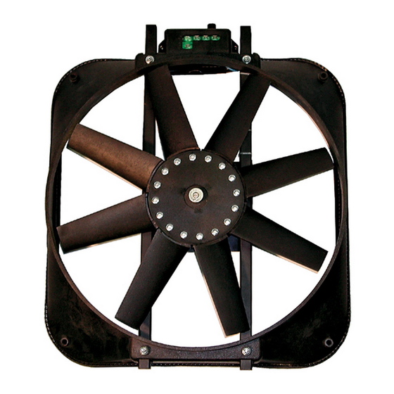
Part #67017,67029
Universal Fan with Thermostat
Part #67015, 67028
15" Mustang Fan with Thermostat
INSTALLATION INSTRUCTIONS
(Fan may be attached to the radiator horizontally or vertically.)
Mount fan with brackets using either the bolt-on or
clamp-on method, and affix the threaded rods and
brackets to the fan accordingly.
NOTE:
• Use star nuts as shown to stabilize the threaded rods.
• The thermostat sensing bulb MUST contact the radiator surface
for accurate temperature readings.
• To avoid damage, do not over-tighten fan to radiator.
REQUIRED CONNECTIONS
1. Disconnect vehicle battery.
2. Attach the positive (+) terminal to a low-amp
12-volt positive (+) power source (such as fuse
box), using the wire provided in the fan kit.
OPTIONAL CONNECTION: Attach the positive
(+) terminal to an ignition source to stop the fan
unit from operating after the entire is tuned off.
3. Connect the "B" terminal to a high-amp 12-volt
positive (+) power source, such as the positive
(+) side of battery or alternator, using the wire
and inline circuit breaker included in kit. Circuit
breaker is marked for proper installation.
4. Connect the "G" terminal to ground (such as
chassis, negative (-) side of battery) using the
wire provided in the kit.
5. With the wire and 3-way connector provided,
splice into the A/C clutch positive (+) wire.
Connect the other end of the wire to the "C"
terminal of the control box. NOTE: Air
conditioning relay activates fan when A/C is
turned on.
6. Adjust thermostat to desired temperature within
180-240° range.
IMPORTANT: If not using an illuminated switch, disconnect the switch ground.
(on reverse side)
MANUAL SWITCH INSTALLATION OPTION
(permits on/off operation manually).
(Switch not included – Must purchase separately)
1. Attach the "M" terminal to terminal 1 on the
switch.
2. Attach terminal 2 to 12-volt positive (+) source.
3. Attach terminal 3 to ground.
Note: To prevent the fan from thermostat
activation, omit the lead to the positive (+) terminal
of the control box, B, G & M must remain
connected.
Control Box Terminals & Connections
12 Volt High Amp Positive
Bolt-on Method
Radiator
Channel
Thermostat
Sensing Bulb
Radiator
Front
Mandatory Connections
+ 12 volt low amp source
G Ground
B 12 volt high amp source
C Air conditioning relay
Control Box
3-way
Connector
M
C
B
Circuit
Breaker
12 Volt Source
Ground
(Illuminate switch – not incl.)
Clamp-on Method
Nut
Bracket
Washer
Threaded
Rod
Star Nut
Optional Connections
M Manual switch
Ground
G
+
12 Volt Low Amp Source
Advertisement

Related Manuals for ProForm 67017

Summary of Contents for ProForm 67017
- Page 1 — CAUTION — FAN BLADES CAN CAUSE INJURY. TO AVOID PERSONAL INJURY, KEEP CLEAR FROM FAN BLADES. FAN BLADES MAY START AT ANY TIME. Part #67017,67029 Universal Fan with Thermostat Bolt-on Method Clamp-on Method Part #67015, 67028 Bracket Radiator Washer 15"...
- Page 2 www.proformparts.com/tech — CAUTION — FAN BLADES CAN CAUSE INJURY. TO AVOID PERSONAL INJURY, KEEP CLEAR FROM FAN BLADES. FAN BLADES MAY START AT ANY TIME. 15" Mustang Fan with Thermostat - Part #67015, 67028 The included bracket (see image A) is used for the overflow tank.
Need help?
Do you have a question about the 67017 and is the answer not in the manual?
Questions and answers