
Subscribe to Our Youtube Channel
Related Manuals for Synectic Electronics SY035


Summary of Contents for Synectic Electronics SY035
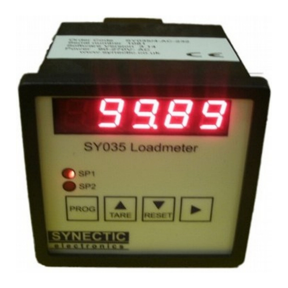
- Page 1 SY035 Weight Indicator User instructions Rev. Sept 2013 Relates to firmware version 3.15...
-
Page 2: Table Of Contents
CONTENTS Specification Operation Tare options Configuration Calibration Filter Least significant digit Peak hold Relays RS232 option Baud rate 4.1a RS485 address Remote display Printer Remote commands Analogue output option 4-20mA calibration Voltage calibration Connections... -
Page 3: Specification
Specification Display 5 digit LED, 10mm character height. Programmable for 0, 1, 2 or 3 decimal points. Range +99999 / -9999 Least significant digit can be set to count in steps of 1,2,5 or 10 Load cell input Direct connection of up to 4 x 350R load cells. An internal amplifier feeds this signal into a 24bit ADC which takes up to 120 readings/sec. -
Page 4: Operation
Operation The display can show live readings or can be set to peak hold mode (see 3.4) which allows peak and trough values to be viewed. 5 digit LED display Setpoint relay status indicators 4 button keypad This button is used to switch the instrument to configuration mode. The TARE button is used in configuration mode to increment digit values and for navigation. -
Page 5: Configuration
Configuration Load cell calibration Press then PROG button then press 5 or 6 until CAL is displayed. Press the 4 key to enter the calibration mode. The instrument can be calibrated to the load cells by adding a known weight. Before adding a known weight, make sure you tare the instrument before entering calibration mode. -
Page 6: Filter
Filter Rates are: Filter Rate(RD 0ff) Rate(RD on) Notes 19msec 26msec 25dB rejection @ 60Hz 19msec 26msec 25dB rejection @ 50Hz 30msec 31msec 50msec 51msec 80dB rejection @ 60Hz 61msec 62msec 65dB reject @ 50 & 60Hz 62msec 63msec 80dB rejection @ 50Hz 105msec 106msec 67dB reject @ 50 &... -
Page 7: Remote Display
Remote Display When the RS232 interface is fitted the option is available to connect a remote display, rdisp such as a unit from the SY033 range. Press the 4 key to indicate state, on or off. With remote display on, anything shown on the LED display, will also be shown on the remote display. -
Page 8: Analogue Output Option
Response Read Unit ID Model number, Firmware version and serial number. Eg. SY035,V3.0, 1234cr Programme heading A heading of up to 46 characters can be programmed to appear on the printout Follow the *H command by the required message, terminated by carriage return if less than 46 characters. -
Page 9: Connections
Connections Power in Setpoint relay 1 Setpoint relay 2 Fuse Analogue output adjustments RS232 Load cell input Remote Tare AC Power input Normally open contact Live to L/+, Earth to E , Neutral to N/-terminals. Link to tare off (zero) Voltage range 95 to 264V displayed reading. - Page 10 If not suppressed this can affect instruments in the vicinity, including the SY035, and significantly reduce the life of the relay contacts. A varistor of the appropriate voltage, or a capacitive suppressor can be used. The ideal way to connect power to the controller and the inductive load is to use two separate power supply’s one to power the controller and one for the contactor, solenoid or relay, if...
Need help?
Do you have a question about the SY035 and is the answer not in the manual?
Questions and answers