Advertisement
Quick Links
NOTICE!
No mixing valve will work satisfactorily if improperly installed. We suggest, therefore, that you read
these instructions carefully before installing and follow directions as outlined. Handle the mixing valve with care.
CAUTION: When maintaining and adjusting the
mixing valve, all fixtures should be isolated from
use. Lawler Manufacturing Co., Inc. recommends
that you work safely at all times and in a manner
consistent with the OSHA Lock/Tagout standard,
29 CFR 1910.147 and other applicable standards.
This installation & maintenance manual covers all
configurations of the 801 including manifold recirculation
systems, multiple valve systems and ARV systems.
WARNING: This product contains chemicals known
to the State of California to cause cancer and birth
defects or other reproductive harm.
(Installer: California law requires that this warning
be given to the consumer.)
For more information: www.oehha.org/prop65
ASSE 1017 Approved
ASSE Lead Free Certified
Certified to CSA B125.3
INSTALLATION &
MAINTENANCE MANUAL
Design and specifications subject to change without notice.
Please refer to temperedwater.com to ensure most
current data sheet and other design solutions.
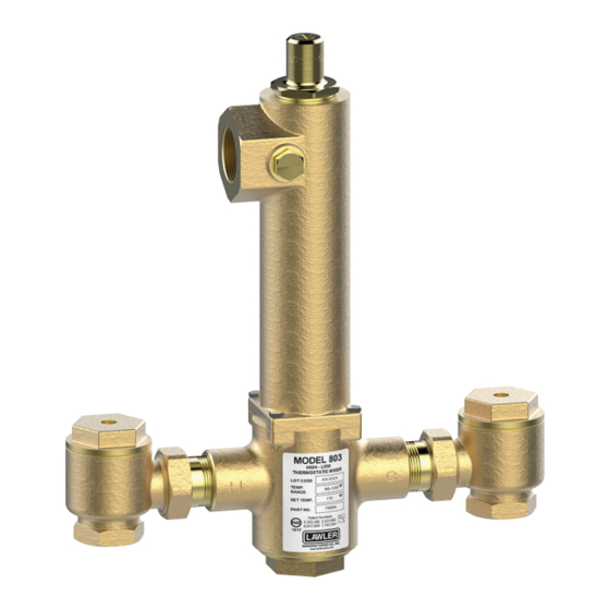
Model 803
Thermostatic Water
Controller
CAPACITIES – MODEL 803
Pressure Drop PSI
5
Valve Number
803-GPM
43
803-LPM
163
1/2 gpm when properly installed in recirculated system.
73004_803_STD_DRW_NODIMS.pdf
B
D
A
C
DIMENSIONS
Valve Number
A N.P.T.
803
1-1/4"
Dimensions are for reference purposes only. For rough-in dimensions
please refer to Lawler's Revit/BIM models found at temperedwater.com.
temperedwater.com
5330 East 25 th St.
Indianapolis, IN 46218
Phone (317) 261-1212
Fax (317) 261-1208
10
20
30
45
60
Capacity
60
85
103
125
144
227
322
390
473
545
A
B N.P.T.
C
1-1/2"
12-3/4"
temperedwater.com/patents
80
165
624
D
12-1/2"
M 803 B
Advertisement

Related Manuals for Lawler 803


Summary of Contents for Lawler 803
- Page 1 12-1/2” Dimensions are for reference purposes only. For rough-in dimensions WARNING: This product contains chemicals known please refer to Lawler’s Revit/BIM models found at temperedwater.com. to the State of California to cause cancer and birth defects or other reproductive harm.
-
Page 2: Maintenance
Performance Checking Hot Water Shut-Off The Model 803 water temperature controller is carefully Allow full hot and cold water to flow through the valve for assembled and tested at the factory to mix hot and cold one minute. Shut off the cold water stop and check valve water to any desired temperature within range. -
Page 3: Testing The Thermostat
Testing the Thermostat Figure A 1. Place a 3/8” 3/8” Wooden Dowel wooden dowel rod into center of thermostat then Reference place in 85°F water. Marks Make a reference mark on the rod as shown in fig. A. 2. Now insert thermostat into hot water that is at least 20°F higher than... -
Page 4: Repair Parts
Model 803 Cut-away Repair Parts Item Description Part No. See Fig. B Screw 7628-00 Adjusting Screw 8237-00 Bonnet Gasket — Dome — Liner O-Ring — Liner — Plunger — Piston Liner Assembly Figure C* Valve Spring — Bottom Plug —... -
Page 5: Typical Installation
GUARANTEE We guarantee the Lawler Mixing Valve to be free from def ects in workmanship and material, and for a period of one year from date of purchase, will replace any parts found by us to be defective. We will not be held responsible, however, for any labor incidental to, or for any damages caused by defective material.