Table of Contents
Advertisement
Advertisement
Table of Contents

Subscribe to Our Youtube Channel
Summary of Contents for Ablerex ATS-16A
- Page 1 Automatic Transfer Switch User Manual ATS-16A/20A/30A/32A...
-
Page 2: Table Of Contents
Table of Contents Safety Instructions .................. 2 Product Description ................3 Installation and Operating Instructions ........... 6 3.1. Packaging ....................6 3.2. Choose an installation location .............. 6 3.3. Product Introduction ................7 ... -
Page 3: Safety Instructions
Safety Instructions SAVE THESE INSTRUCTIONS. This manual contains important instructions that should be followed during installation and maintenance of the ATS. 1. Do not disassemble this product without a technician from the original manufacturer or authorized distributor. Doing so voids your warranty and is also a shock hazard. -
Page 4: Product Description
Product Description ATS Feature: The ATS (Automatic Transfer Switch) features two independent power supply circuits supplying power to the load (as shown in Figure 1 below). In the event of a power failure in the main circuit, the ATS automatically switches to the other circuit to supply power to the load. - Page 5 Procedure for replacing or maintaining ATS module in ITS product 1. To turn “Source Switch” to “Source A” position if ATS module powers load by Source A, otherwise to turn “Source Switch” to “Source B” position. Source A Source B LOAD Output Switch Source Switch...
- Page 6 Source A Source B LOAD Output Switch Source Switch...
-
Page 7: Installation And Operating Instructions
Installation and Operating Instructions 3.1. Packaging 3.1.1. Remove the PE foam. 3.1.2. Inspect accessories ○ RS-232 cable x1 pcs ○ USB cable x1 pcs ○ CD (monitoring software, Setting tool ) x1 pcs ○ User manual ○ Handle and screws x1 set ○... -
Page 8: Product Introduction
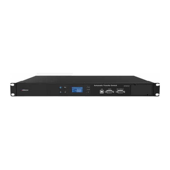
3.3. Product Introduction 3.3.1. Front Panel Item Description/function ○ Mute button Turns off alarm ○ Select source to view info: Input A, Input B, or Source selection button Load ○ Select source info to view: Voltage, current, Info selection button frequency, load capacity ○... - Page 9 3.3.2. LCD Symbol Description/function Input A error or power failure Input B error or power failure Overload System malfunction or abnormal Alarm on Alarm off Digital display showing input/output power connected to load ATS numeric display...
- Page 10 3.3.3. Rear Panel ATS Standard Series: ATS-120(120V-20A) ATS- 130(120V-30A) ATS-216(230V-16A) ATS- 232(230V-32A)
- Page 11 ① ⑤ Output socket Power input (B) ② ⑥ Output breaker Power input (A) ③,④ Input breaker (optional, sold separately) ⑦ Power output...
- Page 12 ITS HOT SWAP Series:...
- Page 13 Input Power (B) Output switch Input Power (A) Normal indicator Cable tie mount Bypass indicator Source switch Output Breaker Source A indicator Output socket Source B indicator Output terminal 3.3.4. Interface The ATS provides three communication ports and one external communication slot (optional) for the user.
- Page 14 3.3.4.3. Dry Contact The ATS provides five user configurable dry contacts for customized features. The capacity of each contact is 24Vdc/1A, additional information is provided in Appendix A. Definition Signal (default) Common 3 Relay 3 Overload Overload time out Relay 4 Common Relay 5 Over temperature...
-
Page 15: Product Installation And Operation
3.4. Product Installation and Operation 3.4.1. Installation Procedure: 1. Open package and note the packaging layers. Keep the box and packaging material in case further transportation is required. 2. Check for damage to the ATS from shipping and handling. Please contact your local distributor if the product is damaged. - Page 16 3.4.2. ATS HOT SWAP Series Installation Steps: 1. Open package and note the packaging layers. Keep the box and packaging material in case further transportation is required. 2. Check for damage to the ATS from shipping and handling. Please contact your local distributor if the product is damaged. 3.
- Page 17 3.4.3. Boot up Once input power is connected, the ATS automatically boots up. The LCD display during boot is as shown in Figure 5 and all LEDs ( are lit. LCD display is as shown in Figure 6 after boot up, only the LEDs for Power A ( ) and Power B ( ) are lit.
-
Page 18: Troubleshooting
Troubleshooting If your ATS is not working normally, use the following status and troubleshooting table to make the appropriate adjustments. Please contact your distributor as soon as possible if the issue cannot be resolved. Issue Possible reason Solution Not connected to the Check the connection from the electrical grid electrical grid to the ATS input... -
Page 19: System Specifications
System Specifications Model ATS-120 ATS-130 ATS-216 ATS-232 Input 100/110/115/120/127 200/208/220/230/240 Input voltage ( +/- 5% / 10% / 15% / 20% ) ( +/- 5% / 10% / 15% / 20% ) Input voltage range 75Vac~150Vac 150Vac~300Vac 50 / 60Hz Input frequency ( +/- 5% / 10% / 15% / 20% ) Input current... - Page 20 Model ITS - 130 ITS - 130F ITS - 232 ITS - 232F Input 100V / 110V / 115V / 120V / 127V 200V / 208V / 220V / 230V / 240V Input voltage (V) (±5%、±10%、±15%、±20%) (±5%、±10%、±15%、±20%) Input voltage 75Vac~150Vac 150Vac~300Vac range Input frequency...
-
Page 21: Appendix A. Dry Contacts Available For Configuration
Appendix A. Dry contacts available for configuration Event Source A voltage abnormal Source B voltage abnormal Source A frequency abnormal Source B frequency abnormal Output Over Load Unit fault (Source A circuit power defected) Unit fault (Source B circuit power defected) Cabinet temperature abnormal Unit fault (Sensor circuit defect) Unit fault (EEPROM data abnormal) -
Page 22: Appendix B. Snmp Card Available Error Code
Appendix B. SNMP Card available Error Code Event Code Source A voltage abnormal Er03 Source B voltage abnormal Er04 Source A frequency abnormal Er05 Source B frequency abnormal Er06 Output Over Load Er16 Unit fault (Source A circuit power defected) Er22 Unit fault (Source B circuit power defected) Er23... -
Page 23: Appendix C. Lcd Available Error Code
Appendix C. LCD available Error Code Event Code Output Over Load Er16 Overload time out Er30 Transferring fail by sync setting condition Er31 Pre-alarm active Er32 Communication connection abnormal Er33... - Page 24 192321342002008...
Need help?
Do you have a question about the ATS-16A and is the answer not in the manual?
Questions and answers